
Interconnect and termination methodology for e-textiles

a technology of electronic textiles and termination methods, applied in the direction of coupling contact members, coupling device connections, electric discharge lamps, etc., can solve the problems of difficult stripping of un-insulated conductive fibers from the surrounding and the woven fabric's insulative material cannot withstand the high temperature of soldering, so as to achieve more reliable connection in terms of electrical conductivity and/or strength

Active Publication Date: 2012-03-22
TE CONNECTIVITY CORP
View PDF10 Cites 44 Cited by
  • Summary
  • Abstract
  • Description
  • Claims
  • Application Information

AI Technical Summary

Benefits of technology

[0006]A need remains for a termination method for e-textiles that creates a more reliable connection in terms of electrical conductivity and/or strength.
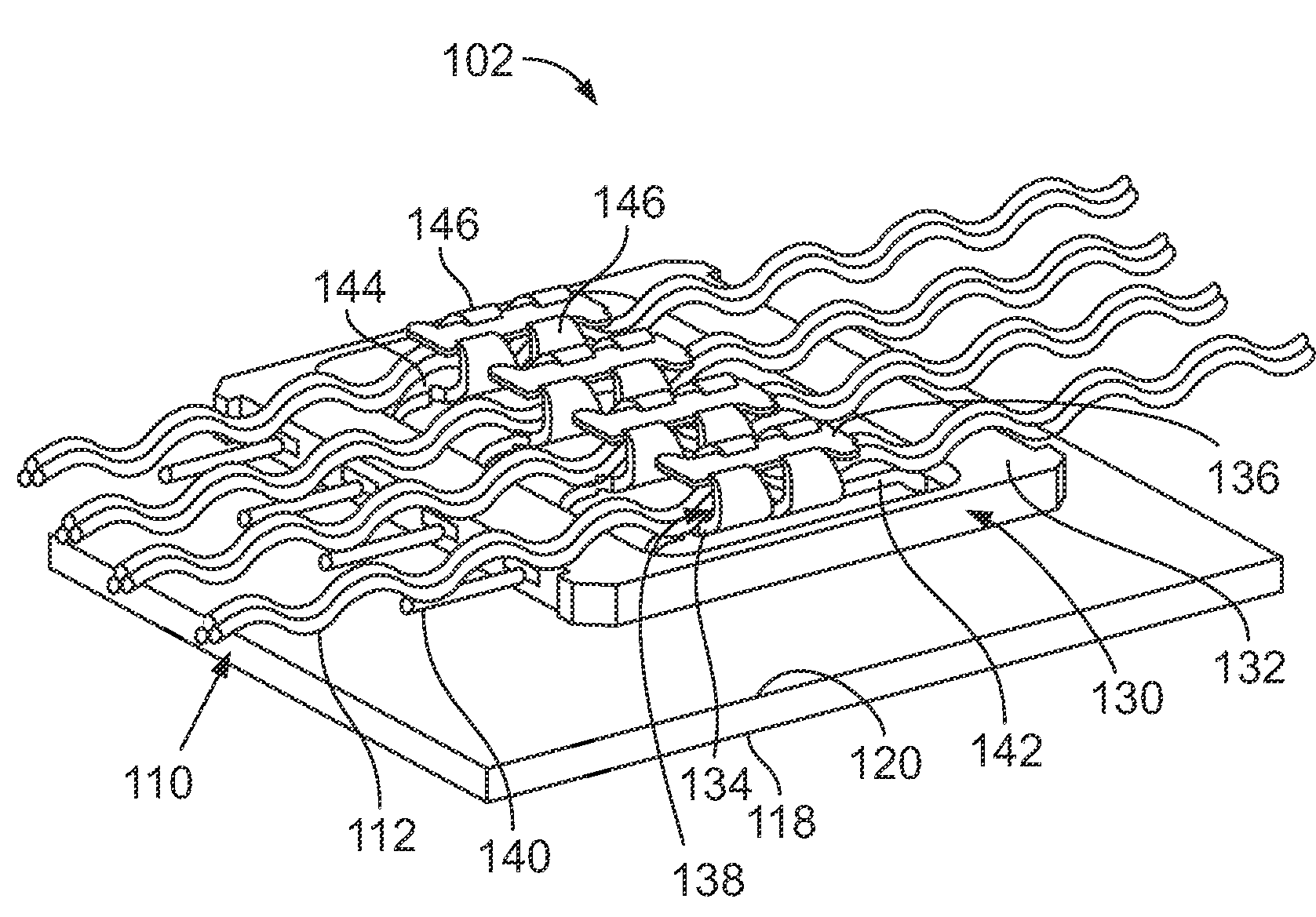
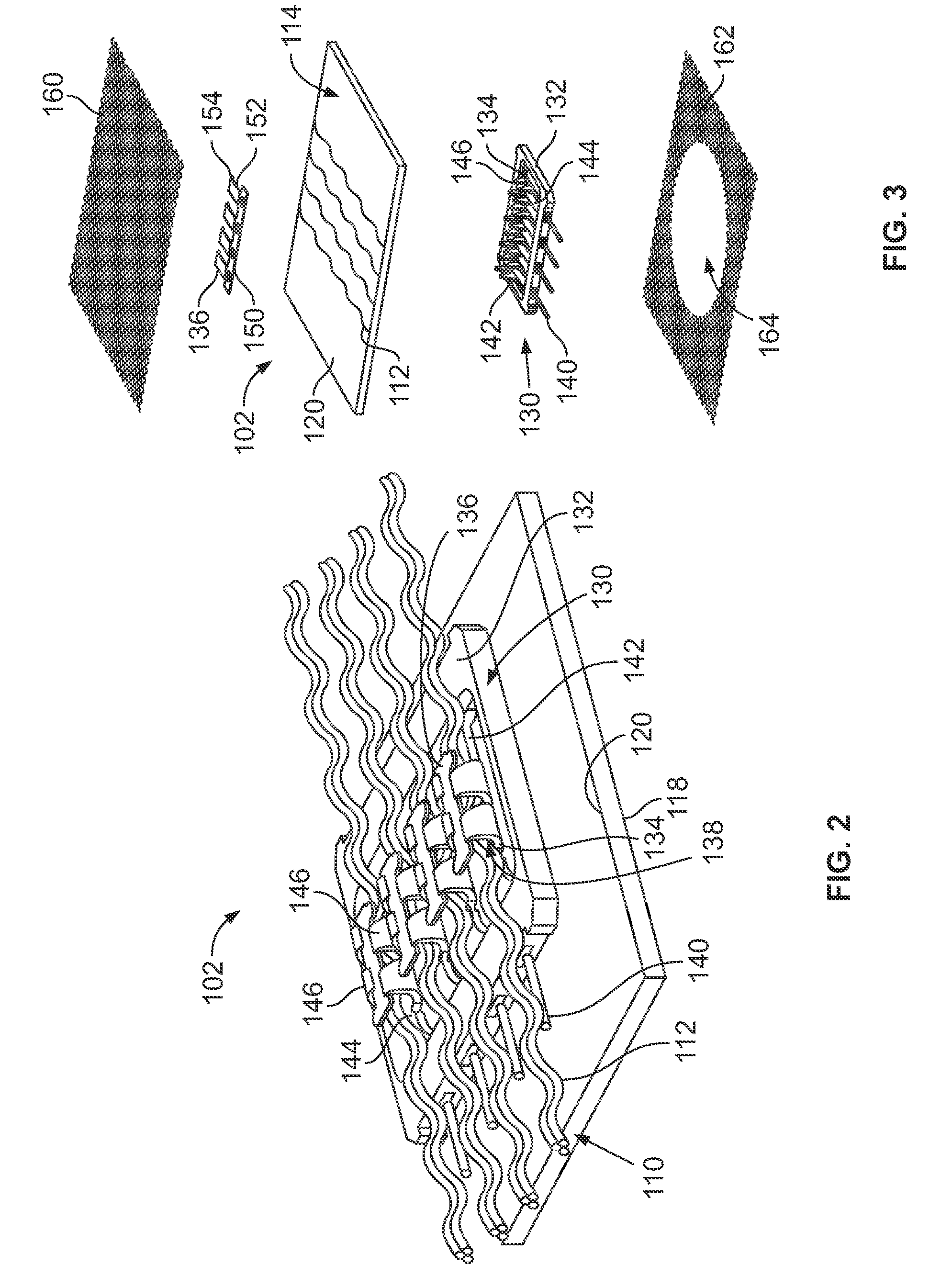
[0007]In one embodiment, a connector is provided for an e-textile that has conductors that define a conductive layer of the e-textile. The connector has a terminal that may have a mating end and a mounting end. The mounting end is configured to be terminated to one or more of the e-textile's conductors. The mating end can be configured to be mated with a mating contact of a mating component and/or mating conn

Problems solved by technology

Soldering poses an issue because it is difficult to strip un-insulated conductive fibers from the surrounding woven fabric's insulative material.
Additionally, the woven fabric's insulative material cannot withstand the high temperatures of soldering.
Furthermore, crimping to un-insulated conductive fibers of e-textiles has proven less reliable and difficult.
However, because the un-insulated conductive fibers are woven into the fabrics, the terminals crimped to the fabrics have few points of contact with the conductive fibers, and thus the electrical connection therebetween is less reliable.

Method used


Image

  • Interconnect and termination methodology for e-textiles
  • Interconnect and termination methodology for e-textiles
  • Interconnect and termination methodology for e-textiles

Examples


Embodiment Construction

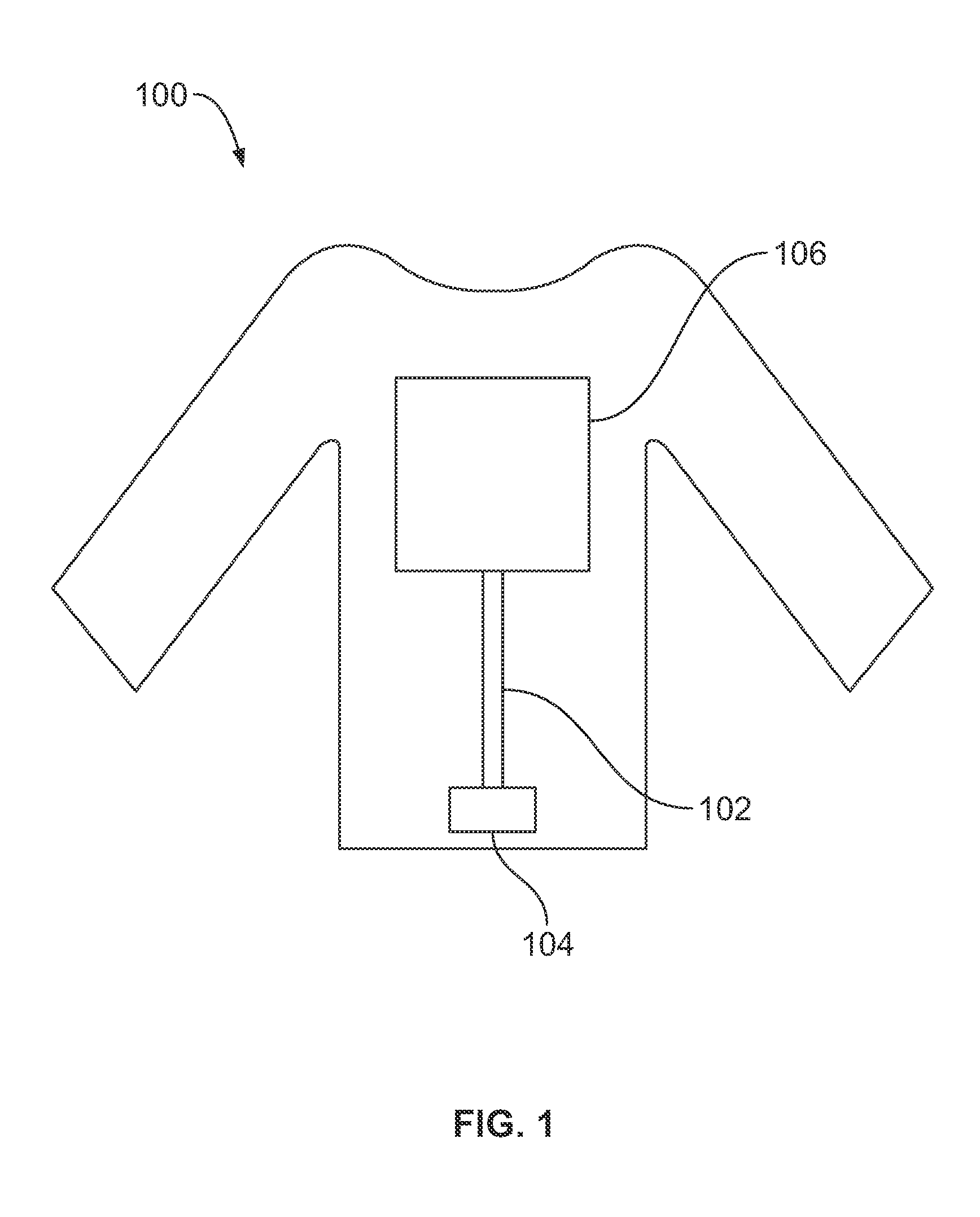
[0021]FIG. 1 illustrates a wearable article 100, such as a garment, that incorporates an electronic textile (e-textile) 102 therein. The e-textile 102 includes fabrics that enable computing, digital components and / or electronics to be embedded therein. The e-textile 102 provides the wearable article 100 with wearable technology that allow for the incorporation of built-in technological elements into the fabric of the garment. The wearable article 100 may constitute intelligent clothing or smart clothing.

[0022]The e-textile 102 extends between a first electronic device 104 and a second electronic device 106. Any number of electronic devices may be utilized with the wearable article 100. In an exemplary embodiment, the first electronic device 104 constitutes a battery pack and the second electronic device 106 constitutes an LED array that may be powered by the battery pack. Other types of electronic devices may be incorporated into the wearable article 100 in alternative embodiments, ...


PUM


Abstract

A connector for an e-textile having a conductive layer that includes conductors includes a terminal and a base separately provided from the terminal. The terminal has a mating end and a mounting end. The mounting end is terminated to the e-textile's conductors. The mating end is configured to be mated with a mating contact of a mating component. The terminal has a body and a plurality of tines extending from the body. The base is arranged opposite the body of the terminal such that the e-textile's conductors are positioned between the base and the body of the terminal. The terminal is crimped to electrically connect the terminal and the base to the e-textile's conductor. The tines are folded against the base to electrically connect the terminal to the base. The body of the terminal and the base engage the e-textile's conductors.

Description

CROSS REFERENCE TO RELATED APPLICATION[0001]The present application relates to and claims priority from Provisional Application Ser. No. 61 / 384,593 filed Sep. 20, 2010, titled “INTERCONNECT OR TERMINATION METHODOLOGY FOR E-TEXTILES”, the complete subject matter of which is hereby expressly incorporated by reference in its entirety.[0002]The present application relates to US Patent Application having docket number AD-00116 (958-4100), titled “CONNECTORS FOR E-TEXTILES” and filed on the same day as the present application, the complete subject matter of which is hereby expressly incorporated by reference in its entirety.BACKGROUND OF THE INVENTION[0003]The subject matter herein relates generally to electronic textiles, and more particularly, to termination methods and interconnects for electronic textiles.[0004]Electronic textiles (e-textiles) are known and used as wearable technology, such as intelligent clothing or smart clothing, that allow for the incorporation of built-in technol...

Claims


Application Information

Patent Timeline
IPC IPC(8): H01R13/02
CPCH01R12/775H01R12/81H01R13/5219H01R13/6591H01R2107/00H01R13/6461H01R13/6477H01R24/84
Inventor DEBOCK, KIMBERLY ANNFABIAN, DAVID JAMESWALTER, RICHARD P.
Owner TE CONNECTIVITY CORP
Learn More