Posterior Cruciate Ligament Support Brace

Active Publication Date: 2012-03-22
OSSUR HF
View PDF1 Cites 11 Cited by
  • Summary
  • Abstract
  • Description
  • Claims
  • Application Information

AI Technical Summary

Benefits of technology

[0010]Other embodiments of the disclosure may also be characterized as a method of bracing a knee. The method can include providing a first torque, on a posterior of a leg's shank, when a first knee flexion angle is 0°. The method can further include providing a second torque, greater than the first torque, on the posterior of the leg's shank, when a second knee flexion angle is between 0° and 105°. The method can also include providing a third torque, less than the second torque, on the posterior of the leg's shank, when a third knee flexion angle is greater than 105°.
[0011]Still further embodiments of the disclosure may be characterized as a method of bracing a knee. The method may include providing a first anterior force on a posterior location of a shank whe

Problems solved by technology

PCLs are often damaged by sports activities, automobile crashes, and various other accidents.
When the PCL is damaged or torn, the knee is considered somewhat unstable.
During this unstable time, it is possible to cause further damage to surrounding ligaments and structures in the knee with normal activity.
During these two weeks following the injury and prior to surgery, the patient's knee can be swollen, stiff, unstable and weak in certain areas of the knee joint and may not

Method used


Image

  • Posterior Cruciate Ligament Support Brace
  • Posterior Cruciate Ligament Support Brace
  • Posterior Cruciate Ligament Support Brace

Examples


Embodiment Construction

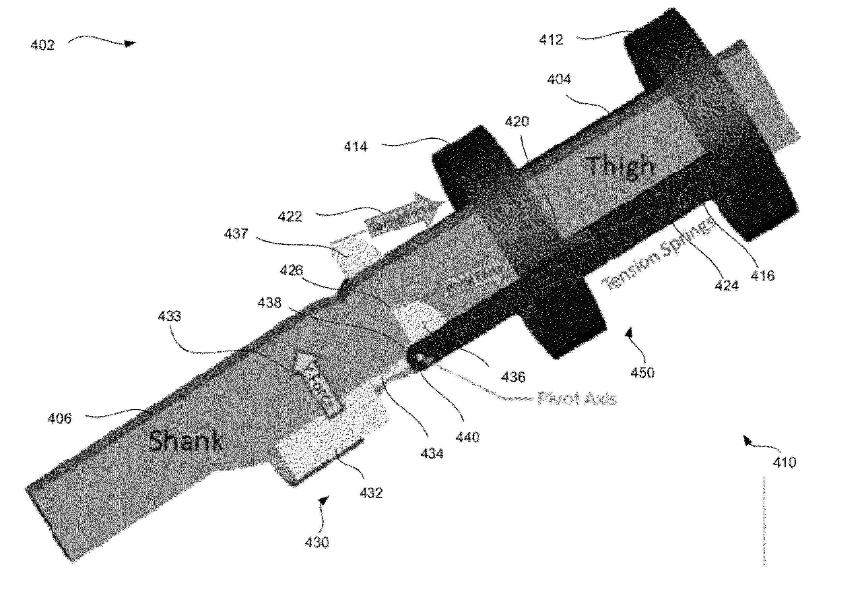
[0029]In general, aspects disclosed herein improve upon prior post-PCL-injury knee braces by using a dynamic rather than static force to resist knee flexion. This dynamic force creates better knee stability through the full range of knee flexion since the dynamic force better replicates the forces of a healthy PCL. This way, before or after surgery, the knee can feel stable without a healthy PCL, the user can avoid further damage to surrounding structures, and the brace improves recovery time, outcomes, and patient satisfaction.

[0030]FIG. 12 illustrates one embodiment of a knee brace 1200 configured for application to a leg 1100 such as that illustrated in FIG. 11. The knee brace 1200 includes a first portion 1202, a second portion 1204, and a coupling element 1206. In the following description the first portion is referred to as the thigh portion and the second portion is referred to as the shank portion. The thigh portion 1202 is configured to engage with, couple to or wrap around...


PUM


Abstract

This disclosure describes systems, methods, and apparatus for a knee brace providing a dynamic resistance or anterior force to a shank of a leg in order to replicate PCL forces of a healthy PCL. A dynamic force dependent upon knee flexion angle provides faster and safer PCL injury healing since the dynamic force better replicates the forces that a healthy PCL would exert on the tibia and femur.

Description

PRIORITY AND RELATED APPLICATIONS[0001]This application claims priority to U.S. Patent Application No. 61 / 383,432 filed on Sep. 16, 2010, and incorporated herein by reference.FIELD OF THE INVENTION[0002]The present disclosure relates generally to orthopedics. In particular, but not by way of limitation, the present disclosure relates to systems, methods and apparatuses for a knee brace resisting knee flexion with a force that depends on the flexion angle.BACKGROUND[0003]The orthopedic medical field frequently recommends that patients use a variety of knee braces to support the knee during everyday activities following an orthopedic injury to the knee, for instance to the posterior cruciate ligament (PCL). PCLs are often damaged by sports activities, automobile crashes, and various other accidents.[0004]The PCL is one of the primary stabilizing structures of the knee, providing stability during motion between the femur and tibia. When the PCL is damaged or torn, the knee is considere...

Claims


Application Information

Patent Timeline
IPC IPC(8): A61F5/00
CPCA61F2005/0179A61F5/0125A61F5/00A61F5/01A61F5/0102A61F5/0123A63B21/00A63B21/02A63B21/04A63B21/045A63B21/0455A63B21/055
Inventor JANSSON, KYLE
Owner OSSUR HF
Why Eureka
Try Eureka