Floating platform for extracting wind energy

a floating platform and wind energy technology, applied in special-purpose vessels, machines/engines, transportation and packaging, etc., can solve the problems of affecting the proper exploitation of wind energy, increasing the difficulty of finding suitable sites for the installation of onshore wind turbines, and increasing the installation, operation and maintenance costs of marine wind energy projects, so as to reduce the movement of floating platforms and improve the effect of performan

Inactive Publication Date: 2012-03-29
APIA XXI SA
View PDF5 Cites 25 Cited by
  • Summary
  • Abstract
  • Description
  • Claims
  • Application Information

AI Technical Summary

Benefits of technology

[0017]The structure has greater transparency to waves and the currents in the areas where volume is not strictly necessary, as, for example, in the lower structure (the area between the float and the ballast). This contributes to a reduction in the floating platform movements and, consequently, an improvement in its performance with respect to other solutions.
[0018]The large diameter of the float tank with respect to other parts of the structure is used as a point of connection of the moorings, and affords a considerable restoring torque for the rotation of the floating platform on its own axis.

Problems solved by technology

Marine wind energy projects have higher installation, operation and maintenance costs than those onshore.
It is increasingly difficult to find suitable sites for the installation of onshore wind turbines.
Thus, patents WO2006132539 and U.S.20070228739 describe two structures whose angles of heel are very high, due to the fact that they do not contemplate the generation of an adequate righting torque.
This impedes the proper exploitation of wind energy by the wind turbine, giving very low yields which can make both systems economically unviable.
Moreover, in the case of patent WO2006132539, part of the structure is made from concrete and, given the necessary volume in an actual construction, it could make the building and transport difficult, given its weight and considering that the difference in cost with certain types of steel is very low.
If a structure of this type wishes to limit its angle of heel, it would need such a large volume that it would be technically and economically unviable to build.
In the absence of a stability system made up of differentiated structures for the floatability of the system, such as a floating tank and a ballast tank, it is not possible to obtain great yields, based on smaller dimensions and lower costs for similar generated power.
Lastly, patent U.S.20060165493 describes a system based on three floating supports, with the resulting proportional rise in costs.

Method used


Image

  • Floating platform for extracting wind energy
  • Floating platform for extracting wind energy

Examples


Embodiment Construction

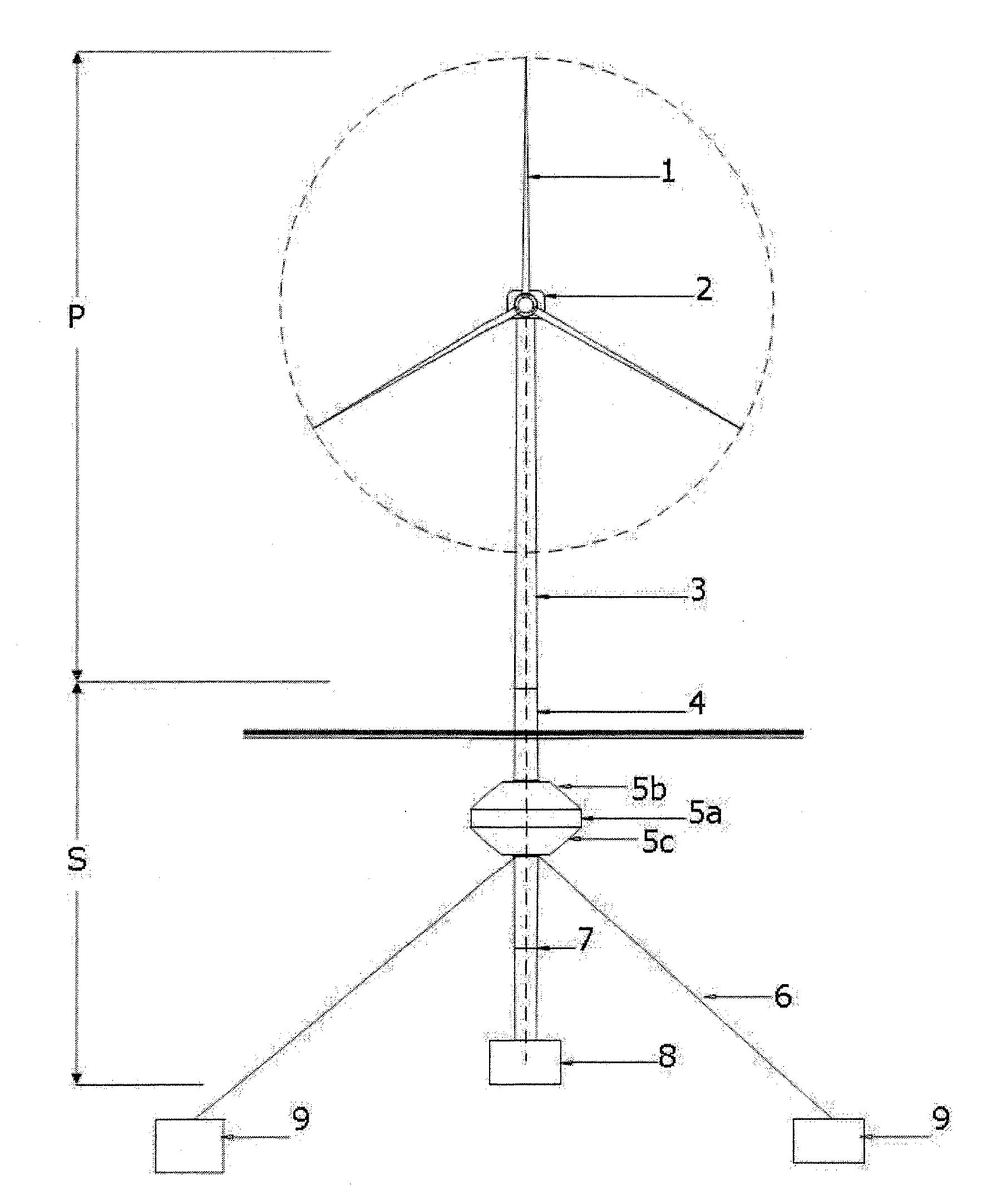
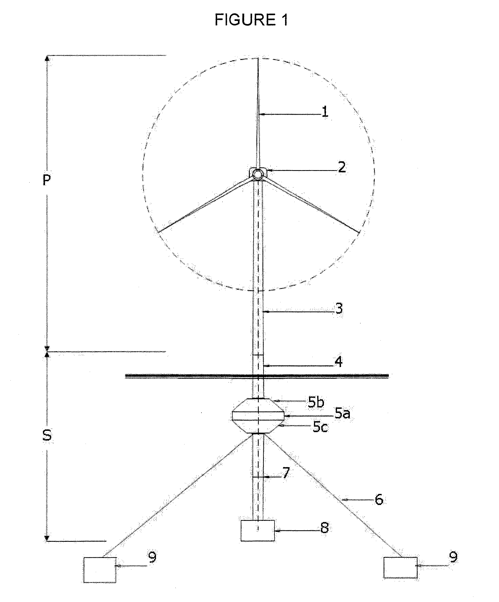
[0008]The floating platform that is the object of the invention is made up of a semi-submerged structure which is anchored to the sea bed by means of a mooring kit. The whole system generates a righting torque thanks to an adequate distribution of weight and volume that guarantees the working of the wind turbine with angles of heel below 10°. The entire structure and its purpose is in itself a novelty, given that no similar structure is currently in operation. This invention solves the problems that arise in seas with depths above 50 m, where it is economically unviable to install wind farms.

[0009]The system's stability is attained thanks to the restoring torque due to the weight-floatability forces torque, and the separation of said forces. The present invention proposes, as a main difference, the creation of a stability system made up of differentiated structures for the floatability of the system—floating tank—and ballasting of the same—ballast tank—, located in the upper part in...


PUM


Abstract

A floating platform for wind energy extraction, comprising a structure (S) which is the support for the assembly (P) made up of a wind turbine tower (3), a nacelle (2) and its corresponding rotor blades (1), whereby the support structure (S) is formed by an upper structure (4) which joins the assembly (P) to the floating tank (5), which is, in turn, joined by means of a lower structure (7) to the ballast tank (8), and whereby said ballast tank (8) is configured to control the assembly's centre of gravity and adjust the flotation line by the distribution of mass.

Description

[0001]The main object of the present invention refers to a floating platform for the generation of electrical energy from wind. This platform can be applied in the field of renewable energies, specifically in the area of so-called off-shore wind energy, that is, at sea and far from the coast.PRIOR ART[0002]Marine wind energy projects have higher installation, operation and maintenance costs than those onshore. The foundations for marine wind turbine towers account for a major part of this initial outlay, which increases with depth, with the result that, currently, at a depth of 50 metres or more, it is economically favourable to use floating platforms.[0003]It is increasingly difficult to find suitable sites for the installation of onshore wind turbines. Consequently, the international tendency is for marine wind farms to be installed in the national waters of each country. However, in many places the water reaches a depth of 50 metres a few kilometres from the shore. As a result, t...

Claims


Application Information

Patent Timeline
Patent Type & Authority Applications(United States)
IPC IPC(8): B63B35/44B63B43/06F03D11/04
CPCB63B35/44B63B2035/446Y02E10/728F05B2240/97Y02E10/727F03D11/04F03D13/25Y02E10/72F03D13/20
Inventor PANTALEON PRIETO, MARCOS J.RAMOS GUITERREZ, OSCAR R.GUTIERREZ MARTINEZ, MIGUEL A.
Owner APIA XXI SA
Why Eureka
Try Eureka