Supercharge Your Innovation With Domain-Expert AI Agents!

Microwave Cavity Detector for Mass Spectrometry

a mass spectrometry and detector technology, applied in the field of mass spectrometers, can solve problems such as limiting the mass resolving power of the spectroscop

Active Publication Date: 2012-03-29
WISCONSIN ALUMNI RES FOUND
View PDF17 Cites 5 Cited by
  • Summary
  • Abstract
  • Description
  • Claims
  • Application Information

AI Technical Summary

Benefits of technology

[0013]It is thus a feature of at least one embodiment of the invention to provide a novel detector for time of flight mass spectrometry providing potentially high temporal resolution.
[0017]It is thus a feature of at least one embodiment of the invention to provide an antenna system effectively capturing energy generated by small charges passing through the cavity.
[0021]It is thus a feature of at least one embodiment of the invention to provide a cavity that can be used in a mass spectrometer without accumulation of material in the cavity.

Problems solved by technology

Conventional spectrometer detectors can exhibit latencies that hide small mass differences for large molecules thus limiting the mass resolving power of the spectroscope.

Method used


Image

  • Microwave Cavity Detector for Mass Spectrometry
  • Microwave Cavity Detector for Mass Spectrometry
  • Microwave Cavity Detector for Mass Spectrometry

Examples


Embodiment Construction

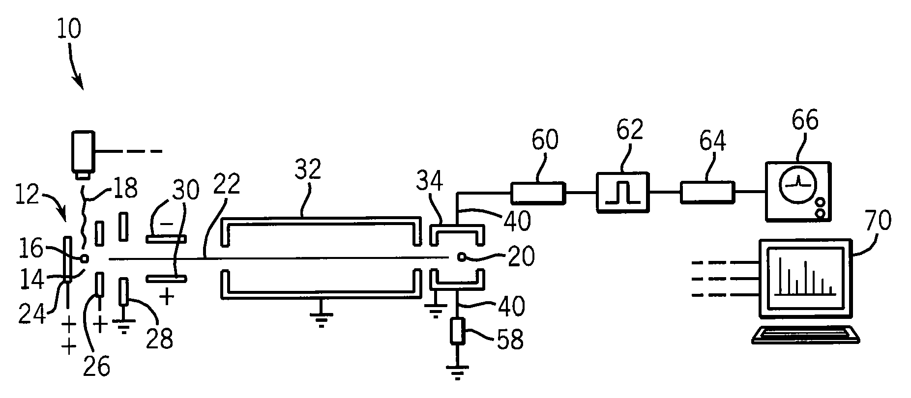
[0031]Referring now to FIG. 1, an example mass spectrometer 10 suitable for use with the present invention may include an ion generator 12, for example, providing an introduction zone 14 into which matrix treated molecules 16 may be introduced and targeted by a laser 18 to provide a source of ions 20.

[0032]The ions 20 may be accelerated along a travel axis 22 by means of various accelerating plates, for example, a repeller plate 24 position on a rear side of the introduction zone 14 and an attractor plate 26 position on the front side of the introduction zone 14 (in the direction of desired ion travel) with the attractor plate 26 having a relatively lower electrical potential than the repeller plate 24 (for positive ions). An accelerator plate 28 in front of the attractor plate 26 may further accelerate the ions 20 to a desired speed. The ions 20 may be focused by a set of steering plates 30 as understood in the art to enter a flight tube 32 providing a zone when the ions 20 of diff...


PUM


Abstract

A detector for time of flight mass spectroscopy uses a microwave resonant cavity excited into resonance by the passage of charged particles as an ion detector. With proper configuration of the frequency of resonance of the cavity, its modes and its quality factor, nanosecond time resolution, should be possible.

Description

STATEMENT REGARDING FEDERALLY SPONSORED RESEARCH OR DEVELOPMENT[0001]This invention was made with United States government support awarded by the following agencies:[0002]USAF / AFOSR FA9550-08-1-0337[0003]The United States government has certain rights to this invention.CROSS REFERENCE TO RELATED APPLICATION[0004]- -BACKGROUND OF THE INVENTION[0005]The present invention relates to mass spectrometers and in particular to a high-resolution detector for time of flight spectrometers.[0006]Mass spectrometers are analytic instruments that may provide for the precise measurement of the mass of molecules. Generally, the molecules to be measured are given an electrical charge and then accelerated by an electrical field. The velocity of their acceleration will be generally proportional to the mass to charge ratio (m / z) and so for a given and known charge the mass may be precisely determined by a velocity measurement.[0007]One method of determining velocity is the use of a “sector” type analyze...

Claims


Application Information

Patent Timeline
IPC IPC(8): H01J49/40H01J49/02
CPCH01J49/40H01J49/025
Inventor BLICK, ROBERT H.PARK, JONGHOO
Owner WISCONSIN ALUMNI RES FOUND
Features
  • R&D
  • Intellectual Property
  • Life Sciences
  • Materials
  • Tech Scout
  • Unparalleled Data Quality
  • Higher Quality Content
  • 60% Fewer Hallucinations
Learn More