Three dimensional image display

a three-dimensional image and display technology, applied in optics, instruments, electrical equipment, etc., can solve the problems of restricted viewing angle, routine use, and inability to use stereoscopic polarization schemes in theaters, and achieve the effect of improving display quality and simple manufacturing process

Active Publication Date: 2012-03-29
SAMSUNG DISPLAY CO LTD
View PDF16 Cites 32 Cited by
  • Summary
  • Abstract
  • Description
  • Claims
  • Application Information

AI Technical Summary

Benefits of technology

[0017]A 3D image display capable of improving display quality by removin

Problems solved by technology

However, because viewers need to wear the separate polarization glasses or the liquid crystal shutter glasses, the stereoscopic polarization scheme is not practical for daily, routine use.
As a result, the stereoscopic polarization scheme has been restrictively used in theaters, etc.
A disadvantage, however, of autostereoscopic systems is that they have a limited viewing angle, and the stereoscopic image can only be viewed at a specific distance and a specific position relative to the display.
A stereoscopic display device that uses a lenticular lens may have a problem in that a black matrix between the color filters is visualized at a specific position.
The view of the black matrix is periodically formed, such

Method used


Image

  • Three dimensional image display
  • Three dimensional image display
  • Three dimensional image display

Examples


Embodiment Construction

[0056]Exemplary embodiments will be described hereinafter with reference to the accompanying drawings. As persons of ordinary skill in the relevant art would realize, the described embodiments may be modified in various different ways, all without departing from the spirit or scope of the invention.

[0057]In the drawings, the thickness of layers, films, panels, regions, etc., are exaggerated for clarity. Like reference numerals designate like elements throughout the specification. It will be understood that when an element such as a layer, film, region, or substrate is referred to as being “on” another element, it can be directly on the other element, or intervening elements may also be present. In contrast, when an element is referred to as being “directly on” another element, there are no intervening elements present.

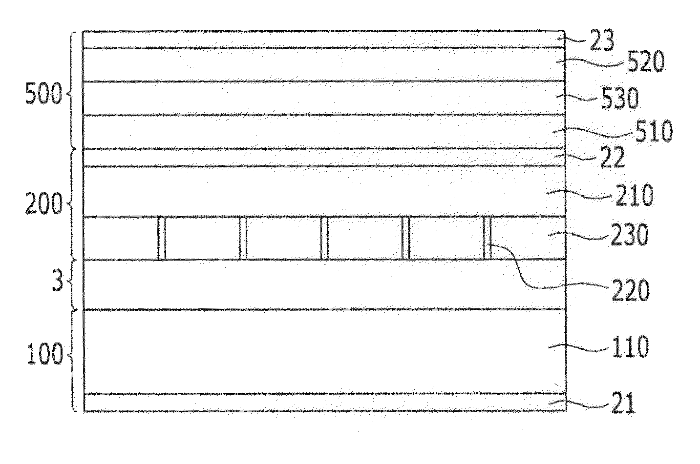
[0058]Hereinafter, a 3D image display according to an exemplary embodiment will be described in detail with reference to the accompanying drawings.

[0059]FIG. 1 is a cr...


PUM


Abstract

A liquid crystal lens unit is provided for use in an autostereoscopic 3D image display. Light passing through the liquid crstyal lens unit is refracted by a liquid crystal layer arranged by an electric field. The voltage levels applied to the to the liquid crystal layer are periodically changed thereby periodically oscillating the position of the focus profile of the liquid crystal lens unit. As a result, moiré patterns are removed and display quality is improved.

Description

CROSS-REFERENCE TO RELATED APPLICATION[0001]This application claims priority to and the benefit of Korean Patent Application No. 10-2010-0093705 filed in the Korean Intellectual Property Office on Sep. 28, 2010, the entire contents of which are incorporated herein by reference.BACKGROUND OF THE INVENTION[0002](a) Field of the Invention[0003]The present invention relates to a three dimensional image display.[0004](b) Description of the Related Art[0005]Currently, the ability to transmit information over communication networks at high speeds has allowed the development of multi-media that provides sight and sound based on a digital terminal processing of characters, audios, videos, etc., at high speeds, and in particular, the development of a three-dimensional stereoscopic information communications. Such three-dimensional stereoscopic information communication services provide a realistic three-dimensional image and accompanying sound to the user.[0006]Generally, a stereoscopic image...

Claims


Application Information

Patent Timeline
IPC IPC(8): H04N13/04G02B30/28
CPCH04N13/0404G02B27/2214H04N13/305G02B30/28G02F1/133512G02F1/133514G02F1/133526G02F1/133528G09G3/3696G02B30/27
Inventor KIM, HWIJUNG, KYUNG-HOLEE, SEUNG-HOONYUN, HAE-YOUNGJEONG, SEUNG-JUNKIM, HEE-SEOP
Owner SAMSUNG DISPLAY CO LTD
Why Eureka
Try Eureka