
Stand-up bag for pourable goods and method for manufacturing the stand-up bag

a technology for pourable goods and stands, which is applied in the direction of paper/cardboard containers, containers, sacks, etc., can solve the problems of difficult control of pouring of packaged products and limited stability, and achieve the effects of convenient stacked and transported, large surface area, and easy stacked and stacked

Active Publication Date: 2012-03-29
NORDENIA DEUTLAND HALLE
View PDF16 Cites 9 Cited by
  • Summary
  • Abstract
  • Description
  • Claims
  • Application Information

AI Technical Summary

Benefits of technology

[0009]The stand-up bag may include a closure device that includes, for example, a pouring element in the form of a pour spout and a cap which allows reclosure. Such pour spouts are usually made of a plastic, and are comparatively rigid. The pour spout may be joined at the top fold and at the front wall and / or back wall in a particularly simple manner by heat sealing which achieves reliable seal-tightness by melting polymers.
[0028]The thickness of the plastic film is largely dependent on the bag size and the filling weight for which the stand-up bag is designed. A stand-up bag for liquids, having a filling volume of approximately 2.5 liters, may be made, for example, of a plastic film having a three-layer structure composed of an outer PET layer 12 μm thick, a PET interlayer 12 μm thick, and a polyethylene layer 100 μm thick at the inner side of the bag. Lastly, to increase the drop strength, fabric may also be introduced into the film composite. Such a plastic film has, for example, a layer composite composed of PE / fabric / PE.

Problems solved by technology

The bag must be handled with both hands, since the spout, as a result of its central location above the back wall, has only limited stability.
Accordingly, is difficult to control pouring of the packaged product, and in particular, precisely pouring the product into a filling opening or the like.

Method used


Image

  • Stand-up bag for pourable goods and method for manufacturing the stand-up bag
  • Stand-up bag for pourable goods and method for manufacturing the stand-up bag
  • Stand-up bag for pourable goods and method for manufacturing the stand-up bag

Examples


Embodiment Construction

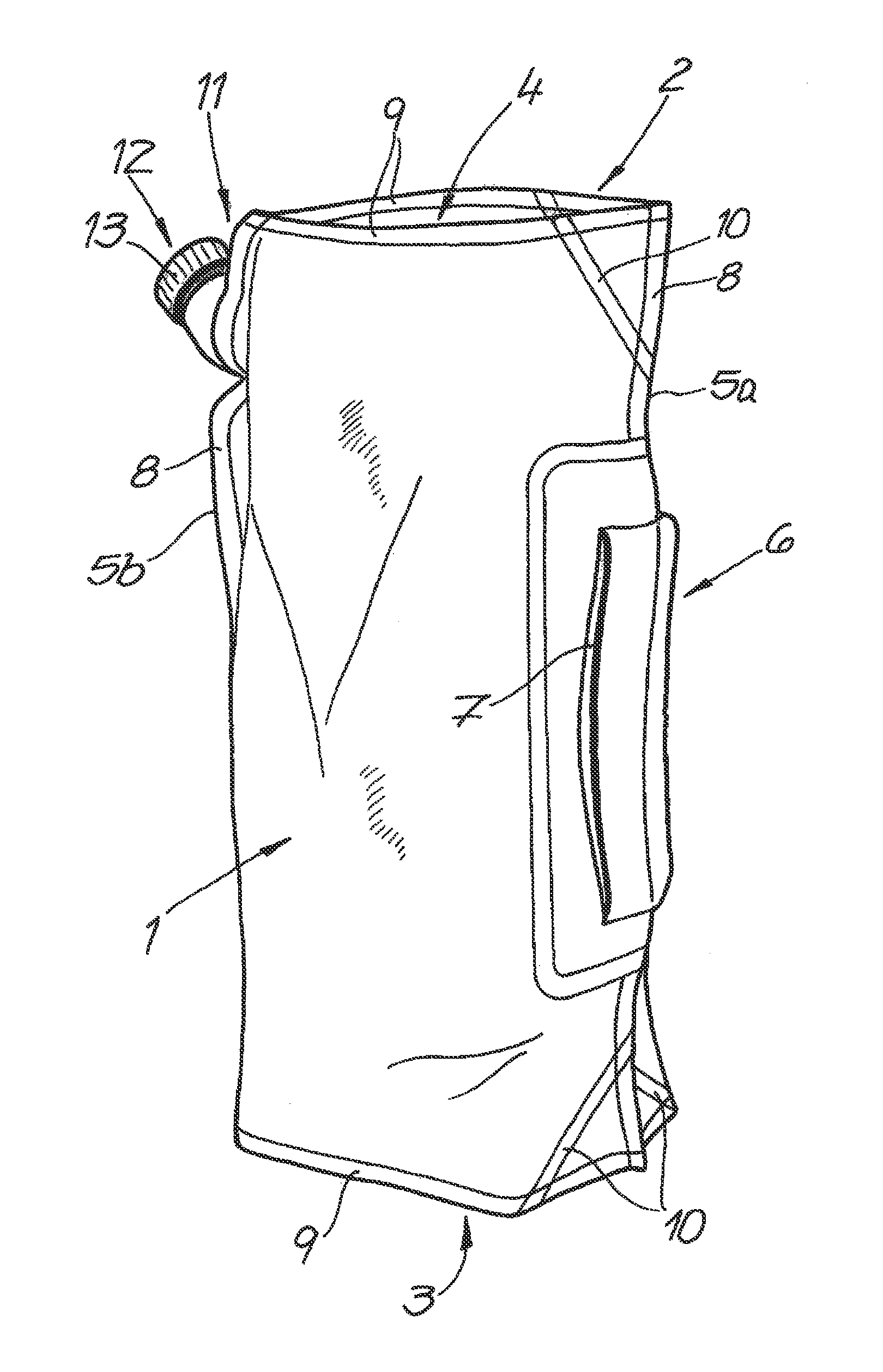
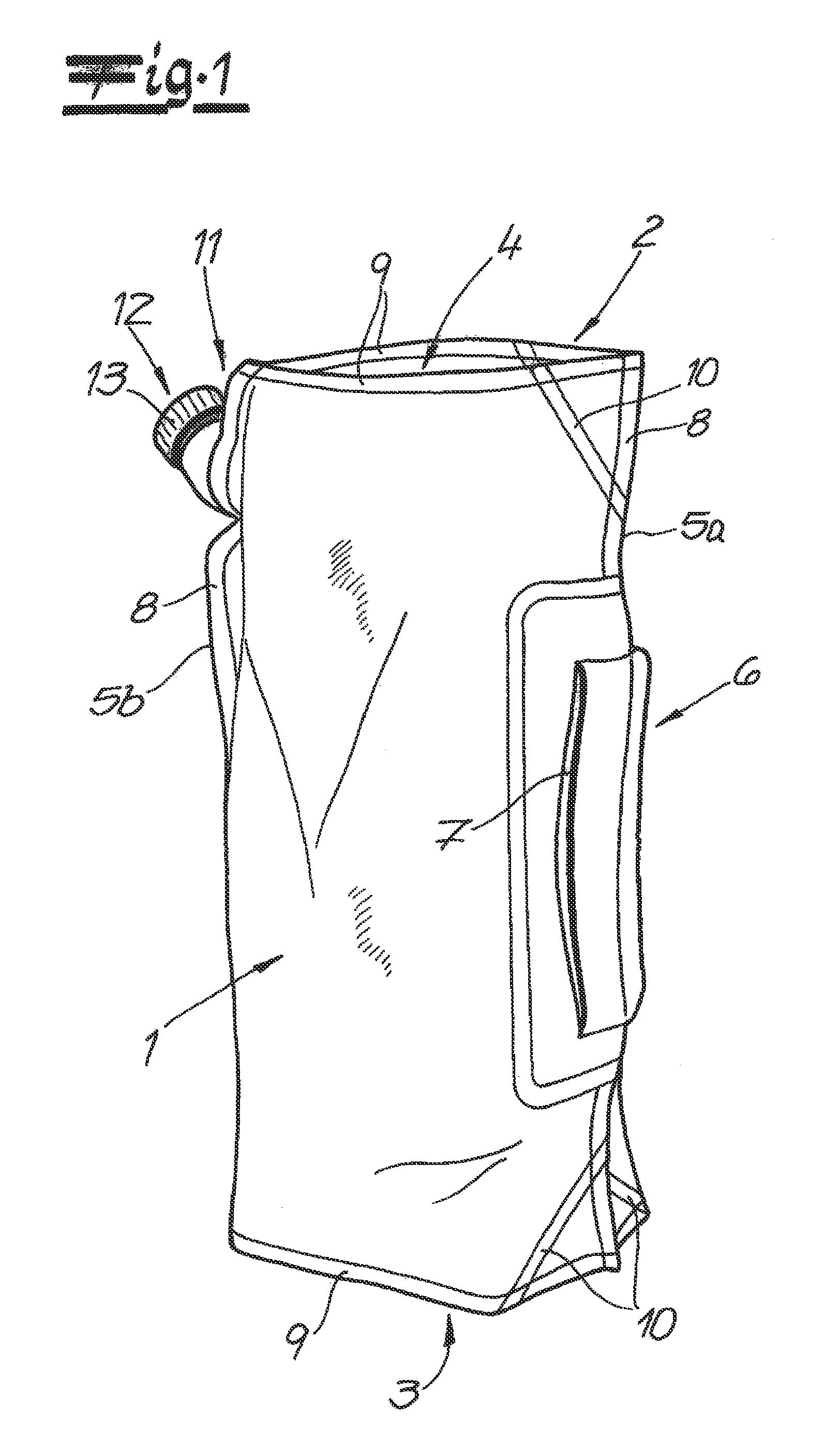
[0045]FIG. 1 shows a stand-up bag for pourable goods that includes a front wall 1, a back wall 2, a base fold 3, and a top fold 4 which are formed from film. The front wall 1 and the back wall 2 are joined together at a first side edge 5a and at a second side edge 5b. Situated in the vertical direction, halfway up at the first side edge 5a, is a carrying handle 6, which in the exemplary embodiment includes a separate film strip 7. The bag is indented in the region of the carrying handle at the front wall 1 and the back wall 2, and the film strip 7 together with the indented region forms a carrying strap which may be accessed from the side. In one embodiment, the carrying strap is initially integrated into the outer surface of the stand-up bag and accessible through a perforation (not illustrated) once the perforation is torn open.

[0046]According to the exemplary embodiment, FIG. 1 shows that the front wall 1 and the back wall 2 are jointly formed from a film cutting, or film section...


PUM

PropertyMeasurementUnit
Distanceaaaaaaaaaa

Abstract

A stand-up bag for pourable goods includes a front wall, a back wall coupled to the front wall at a first side edge and an opposite second side edge, and a base fold, wherein the front wall, the back wall, and the base fold are manufactured from a film, and wherein the base fold provides a standing base and is coupled to lower edges of the front wall and the back wall. The bag further includes a bag top situated opposite from the base fold, a closure device, wherein the closure device is attached proximate the bag top, and a carrying handle on the first side edge between the base fold and the bag top, the carrying handle positioned a distance from the base fold and the bag top.

Description

CROSS REFERENCE TO RELATED APPLICATIONS[0001]This application claims the benefit of European Patent Application No. EP 10 180 334.4 filed Sep. 27, 2010, which is hereby incorporated by reference in its entirety.BACKGROUND OF THE INVENTION[0002]The field of the invention relates generally to a stand-up bag for pourable goods and, more particularly, to a stand-up bag made from a film having a front wall, a back wall, a base fold, a bag top, and a closure device attached proximate the bag top. The field of the invention further relates to a method for manufacturing a stand-up bag.[0003]At least some known stand-up bags are described in European Patent Application Nos. EP 0 772 554 B1, EP 1 233 915 B1, and EP 1 737 752 B1. The stand-up bags described in these references have a pour spout with a screw-on closure which is centrally attached at the upper edge of the stand-up bag, between the front wall and a flap of a top fold provided at the bag top. When filled, the stand-up bags in thes...

Claims


Application Information

Patent Timeline
IPC IPC(8): B65D33/06B31B1/64B31B50/64
CPCB31B37/00B31B2219/145B31B2219/23B31B2219/9054B31B2219/9077B65D75/5883B31B2221/20B31B2221/50B31B2237/20B65D75/008B65D75/56B31B2219/9096B31B70/16B31B2150/00B31B2155/00B31B2160/20B31B70/008B31B70/844B31B70/864B31B70/876B31B2150/002B31B2170/20B31B2155/001B65D33/06
Inventor KRUSE, ALFONSBRAUER, JOCHEN
Owner NORDENIA DEUTLAND HALLE
Learn More