Intelligent Electronic Device and Method Thereof

a technology of intelligent electronic devices and intelligent measurement, applied in the direction of power measurement by digital technique, sustainable buildings, instruments, etc., can solve the problems of detriment to the operability and/or accuracy of the measurement performed by the intelligent measurement device, and achieve the effect of facilitating execution of the method or portions thereo

Active Publication Date: 2012-03-29
ELECTRO INDUSTRIES GAUGE TECH
View PDF3 Cites 41 Cited by
  • Summary
  • Abstract
  • Description
  • Claims
  • Application Information

AI Technical Summary

Benefits of technology

[0010]In a further aspect, a method of measuring supply voltages and currents of an AC electrical service using an intelligent electronic device includes (a) monitoring the supply voltages or the supply currents using a sensing circuit of the device; and (b) selectively adjusting operating ranges of at least a portion of output signals of the sensing circuit to match at least one pre-determined range for input signals of a data acquisition system of the device, wherein the at least one pre-determined range includes a pre-determined range for voltages and a pre-determined range for currents. A computer readable medium storing a program code that, when executed by a computer, facilitates execution of the method or portions thereof is also provided.
[0015]A method of measuring or calculating at least one parameter of an AC electrical service using an intelligent electronic device is provided including (a) forming first measuring channels time-locked to zero-crossing points of supply voltages or supply currents of the AC electrical service; and (b) forming second measuring channels time-locked to pre-determined moments of time. The zero-crossing points are moments of time when a polarity of the supply voltages or the supply currents changes from a negative polarity to a positive polarity or when a polarity of the supply voltages or the supply currents changes from a positive polarity to a negative polarity. In one aspect, step (a) includes measuring or calculating the at least one parameter during a pre-determined number of cycles of an AC frequency of the AC electrical service, wherein the at least one parameter is selected from the group consisting of a line voltage, a line current, a phase voltage, a phase current, or a root mean square (RMS) value thereof; energy, revenue, real power, reactive power, total power, and a power factor. In a different aspect, the step (a) includes measuring or calculating the at least one parameter during a pre-determined time interval, wherein the at least one parameter is selected from the group consisting of a waveform of a line voltage, a waveform of a line current, a waveform of a phase voltage, a waveform of a phase current; and a total harmonic distortion or harmonics thereof. A computer readable medium storing a program code that, when executed by a computer, facilitates execution of the method of or portions thereof is also provided.
[0025]In yet aspect, a method of presenting a fractional numerical value in a digital data format, includes forming a datagram having a pre-determined number of the data segments; and assigning to contents of the data segments numerical values providing that an average numerical value of the contents is equal to the fractional numerical value, wherein the fractional numerical value is an instantaneous numerical value of at least one parameter of an AC electrical service selected from the group consisting of a line voltage, a line current, a phase voltage, a phase current, and a total harmonic distortion (THD) or a root mean square (RMS) value thereof; energy, revenue, real power, reactive power, total power, and a power factor. A computer readable medium storing a program code that, when executed by a computer, facilitates execution of the method or portions thereof is also provided.

Problems solved by technology

While it is efficient to use a single model of a respective IED by different groups of customers or in different electrical networks, exposure of the IED to multiple ranges of supply voltages and currents may have a detrimental effect on its operability and / or accuracy of the measurements performed by the IED.

Method used


Image

  • Intelligent Electronic Device and Method Thereof
  • Intelligent Electronic Device and Method Thereof
  • Intelligent Electronic Device and Method Thereof

Examples


Embodiment Construction

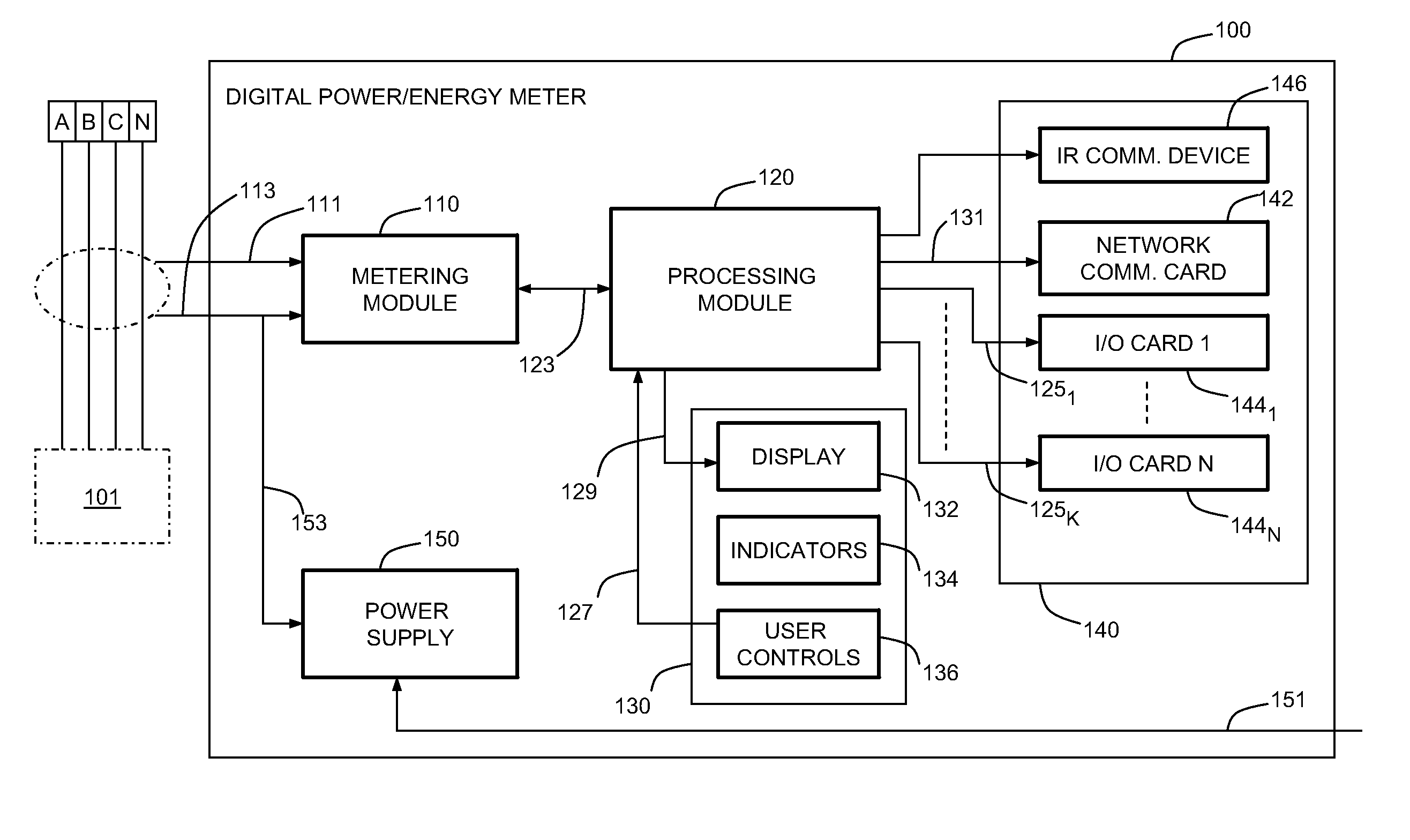
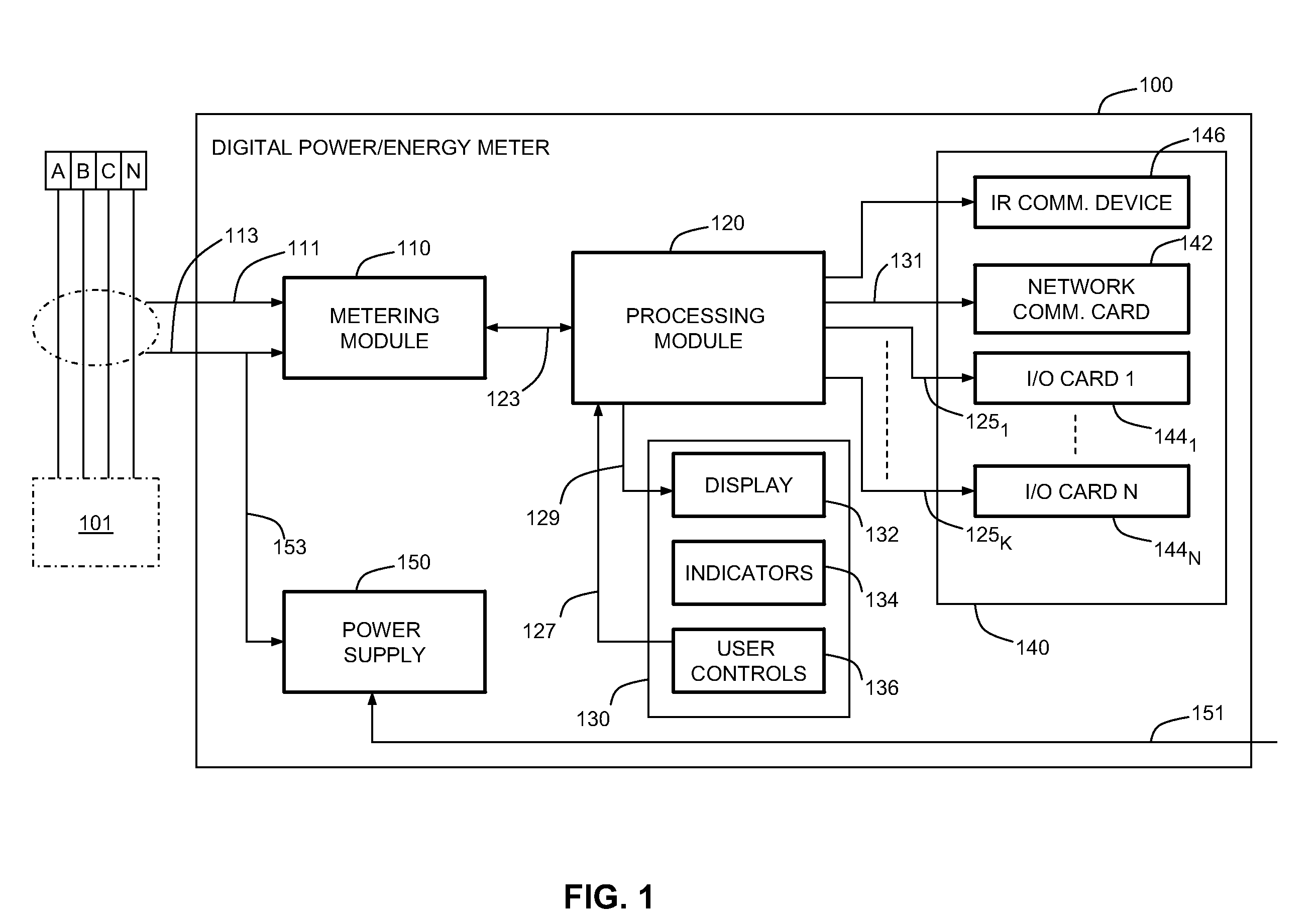
[0075]Aspects of the present disclosure are illustratively described herein within the context of digital electrical power and energy meters, including revenue accuracy certifiable meters. The term “digital electrical power and energy meters” is broadly used herein in reference to IEDs adapted to record, measure, or communicate at least some of supply currents and supply voltages of the respective electrical service, their waveforms, harmonics, transients, and other disturbances, and the corresponding parameters, such as power, power quality, energy, revenue, and the like. Moreover, a variety of electrical service environments may employ IEDs and, in particular, may employ digital electrical power and energy meters. By way of example and not limitation, these environments include power generation facilities (e.g., hydroelectric plants, nuclear power plants, etc.), power distribution networks and facilities, industrial process environments (e.g., factories, refineries, etc.), and bac...


PUM


Abstract

An intelligent electronic device (IED) having a gain control unit adapted to selectively regulate operating ranges of output signals of a sensing circuit of the device is described. In one embodiment, the IED is a digital electric power and energy meter, which operating ranges for supply voltages and supply currents of electrical services may be adjusted to match pre-determined ranges for input signals of a data acquisition system or a data processing module of the meter.

Description

CROSS-REFERENCE TO RELATED PATENT APPLICATIONS[0001]This application is a continuation application of U.S. patent application Ser. No. 12 / 056,955 filed on Mar. 27, 2008, which is a continuation-in-part application of U.S. patent application Ser. No. 12 / 036,356 filed on Feb. 25, 2008, which is a continuation application of U.S. patent application Ser. No. 11 / 341,802 filed on Jan. 27, 2006 entitled “METERING DEVICE WITH CONTROL FUNCTIONALITY AND METHOD THEREOF”, now U.S. Pat. No. 7,337,081, which claims priority to U.S. Provisional Patent Application Ser. No. 60 / 647,669 filed on Jan. 27, 2005, the contents of which are hereby incorporated by reference in their entireties.[0002]This application also claims priority to U.S. Provisional Patent Application No. 60 / 920,198, filed on Mar. 27, 2007, which is herein incorporated by reference.FIELD OF THE INVENTION[0003]The present disclosure relates generally to the field of intelligent electronic devices for electrical utility services and, m...

Claims


Application Information

Patent Timeline
Patent Type & Authority Applications(United States)
IPC IPC(8): G01R19/00
CPCG01D4/004G01R22/10G01R21/133Y02B90/242Y04S20/322Y04S20/30Y02B90/20
Inventor BANHEGYESI, TIBORKAGAN, ERRANBANKER, PATRICIA E.
Owner ELECTRO INDUSTRIES GAUGE TECH
Why Eureka
Try Eureka