
Methods for dynamic consistency group formation and systems using the same

a dynamic consistency and group technology, applied in the field of data storage systems, can solve the problems of increased latency affecting the performance and viability of storage systems, inability to write and migrate operations, and data collisions, so as to and minimize collisions affecting data

Inactive Publication Date: 2012-03-29
IBM CORP
View PDF8 Cites 70 Cited by
  • Summary
  • Abstract
  • Description
  • Claims
  • Application Information

AI Technical Summary

Benefits of technology

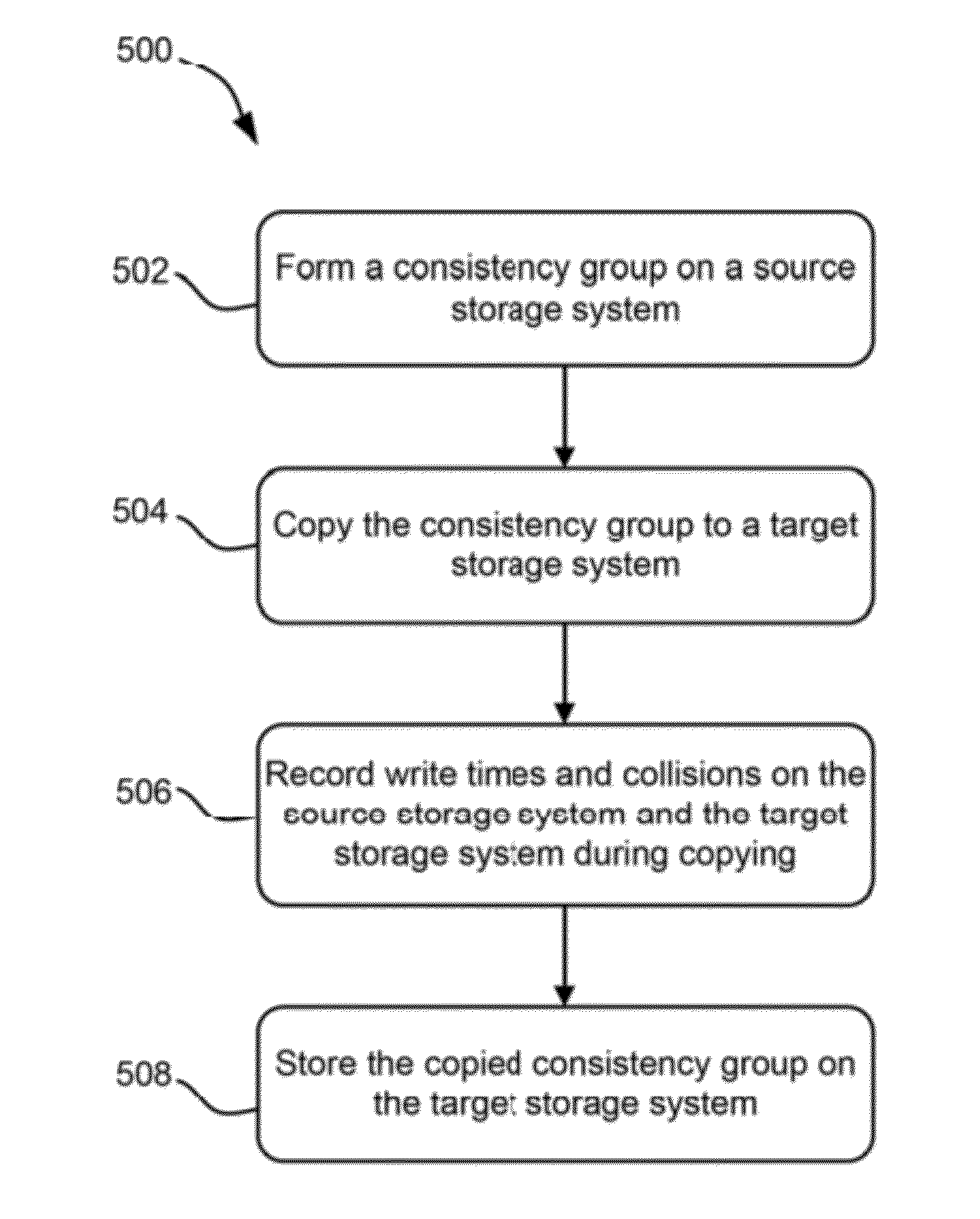
[0009]In one embodiment, a method for dynamic consistency group formation includes: creating a snapshot of first data stored on a source storage system, wherein the snapshot is a logical copy of the first data stored on the source storage system with respect to data content and data structure; copying the snapshot to a target storage system; copying the first data represented by the snapshot from the source storage system to the target storage system; detecting one or more write operations affecting data on the source storage system; detecting one or more collisions affecting the first data on the source storage system, wherein a collision occurs whenever the one or more write operations affect at least a portion of the first data prior to the at least a portion of the first data being written to the target storage system; setting a consistency group interval, wherein the consistency group interval represents an interval duration between successive snapshot create-and-copy events; and altering the consistency group interval to minimize collisions affecting data on at least one of the storage systems.
[0010]In another embodiment, a system includes: logic for creating a snapshot of first data stored on a source storage system, wherein the snapshot is a logical copy of the first data stored on the source storage system with respect to data content and data structure; logic for copying the snapshot to a target storage system; logic for copying the first data represented by the snapshot from the source storage system to the target storage system; logic for detecting one or more write operations affecting data on the source storage system; logic for detecting one or more collisions affecting the first data on the source storage system, wherein a collision occurs whenever the one or more write operations affect at least a portion of the first data prior to the at least a portion of the first data being written to the target storage system; logic for setting a consistency group interval, wherein the consistency group interval represents an interval duration between successive snapshot create-and-copy events; and logic for altering the consistency group interval to minimize collisions affecting data on at least one of the storage systems.
[0011]In yet another embodiment, a computer program product for optimizing dynamic consistency group formation includes: a computer readable storage medium having computer readable program code embodied therewith, the computer readable program code comprising: computer readable program code configured to create a snapshot of first data stored on a source storage system, wherein the snapshot is a logical copy of the first data stored on the source storage system with respect to data content and data structure; computer readable program code configured to copy the snapshot to a target storage system; computer readable program code configured to copy the first data represented by the snapshot from the source storage system to the target storage system; computer readable program code configured to detect one or more write operations affecting data on the source storage system; computer readable program code configured to detect one or more collisions affecting the first data on the source storage system, wherein a collision occurs whenever the one or more write operations affect at least a portion of the first data prior to the at least a portion of the first data being written to the target storage system; computer readable program code configured to set a consistency group interval, wherein the consistency group interval represents an interval duration between successive snapshot create-and-copy events; and computer readable program code configured to alter the previously set consistency group interval to minimize collisions affecting data on at least one of the storage systems.

Problems solved by technology

Since migration of data to the target storage system often occurs concurrent to writing the data to the source storage system or using the data on the source storage system, events occur where data being written is simultaneously being accessed and / or changed on another system, known as collisions.
These collisions dictate that the migration to the target storage system wait for completion of the corresponding write operation to the source storage system, resulting in unacceptable latency during write and migrate operations.
In an increasingly global economy, where business often occurs internationally and storage needs span the globe, increased latency affects the performance and viability of storage systems, particularly when considering that the distance between the source storage system and the target storage system, which is quite common in the global economy, greatly amplifies the latency experienced during a given collision.
This solution guarantees consistency among the source data and target data, but also results in collisions.
Therefore, symmetrical storage solutions suffer from latency that detracts from data accessibility and inhibits or even prohibits deployment of the storage solutions in practice.
Asymmetrical storage solutions do not suffer from collisions as frequently as symmetrical solutions, since the data transmission is unidirectional, but neither can they guarantee consistency, especially with regard to data structure.
Therefore, asymmetrical storage solutions are inadequate to meet current industry data consistency needs.

Method used


Image

  • Methods for dynamic consistency group formation and systems using the same
  • Methods for dynamic consistency group formation and systems using the same
  • Methods for dynamic consistency group formation and systems using the same

Examples


Embodiment Construction

[0022]The following description is made for the purpose of illustrating the general principles of the present invention and is not meant to limit the inventive concepts claimed herein. Further, particular features described herein can be used in combination with other described features in each of the various possible combinations and permutations.

[0023]Unless otherwise specifically defined herein, all terms are to be given their broadest possible interpretation including meanings implied from the specification as well as meanings understood by those skilled in the art and / or as defined in dictionaries, treatises, etc.

[0024]It may also be noted that, as used in the specification and the appended claims, the singular forms “a,”“an,” and “the” include plural referents unless otherwise specified.

[0025]The following description discloses several preferred embodiments of storage systems, as well as operation and / or component parts thereof.

[0026]In one general embodiment, a method for dyn...


PUM


Abstract

A method for dynamic consistency group formation, in one embodiment, includes creating a snapshot of first data stored on a source storage system with respect to data content and data structure, copying the snapshot to a target storage system, detecting one or more write operations affecting data on the source storage system while copying the first data, detecting one or more collisions affecting the first data on the source storage system, wherein a collision occurs whenever the write operations affect the first data prior to the first data being written, setting a consistency group interval which represents an interval duration between successive snapshot create-and-copy events, and altering the consistency group interval to minimize collisions affecting data on at least one of the storage systems. Other methods, systems, and computer program products for dynamic consistency group formation are also described.

Description

BACKGROUND[0001]The present invention relates to data storage systems, and more particularly, this invention relates to a method for dynamic consistency group formation in a storage system.[0002]A possible and continuing goal in the data storage industry is that of data consistency, which has become a focal feature of modern data storage systems. The continuing benefit for increasing consistency has spawned an industry dedicated to providing storage solutions to enterprise customers with huge storage capacity and stringent data consistency requirements.[0003]Data stored on a source storage system and a target storage system should be consistent with respect to both data content and data structure. As such, data are typically migrated to the target storage system in the same order as they were written to the source storage system. Since migration of data to the target storage system often occurs concurrent to writing the data to the source storage system or using the data on the sour...

Claims


Application Information

Patent Timeline
Patent Type & Authority Applications(United States)
IPC IPC(8): G06F17/30
CPCG06F17/30215G06F2201/84G06F11/2064G06F16/1844
Inventor JENNAS, II, PAUL A.PEIPELMAN, JASON L.RHOADES, JOSHUA M.WARD, MATTHEW J.
Owner IBM CORP
Learn More