Calibration of focus error signal offset in a focus servo system

a technology of optical disk drive and focus servo, which is applied in the direction of data recording, instruments, disposition/mounting of heads, etc., can solve the problems of large form factor requirements, explosive need for compact data storage, and cost associated with establishing and maintaining optical alignment between components, so as to minimize data jitter, optimize optical disk drive performance characteristics, and maximize peak-to-peak

Inactive Publication Date: 2006-08-15
RPX CORP
View PDF60 Cites 14 Cited by
  • Summary
  • Abstract
  • Description
  • Claims
  • Application Information

AI Technical Summary

Benefits of technology

[0019]In some embodiments, optimizing the servo function includes adjusting the focus error signal offset to maximize a peak-to-peak value of a tracking error signal. In some embodiments, optimizing the read function includes adjusting the focus error signal offset to minimize a data jitter while reading data from an optical media.

Problems solved by technology

The need for compact data storage is explosively increasing.
Regardless of the cause being provided for relative movement between optical components, such an approach, while perhaps useful for accommodating relatively large or massive components, presents certain disadvantages for more compact usage.
These disadvantages include a requirement for large form factors, the cost associated with establishing and maintaining optical alignment between components which must be made moveable with respect to one another, and the power required to perform operations on more massive drive components.
Such alignment often involves manual and / or individual alignment or adjustment procedures which can undesirably increase manufacturing or fabrication costs for a reader / writer, as well as contributing to costs of design, maintenance, repair, and the like.
Additionally, a smaller, more compact, optical head provides numerous specific problems for electronics designed to control the position and focus of the optical head.

Method used


Image

  • Calibration of focus error signal offset in a focus servo system
  • Calibration of focus error signal offset in a focus servo system
  • Calibration of focus error signal offset in a focus servo system

Examples


Embodiment Construction

of an Optical Drive Controller

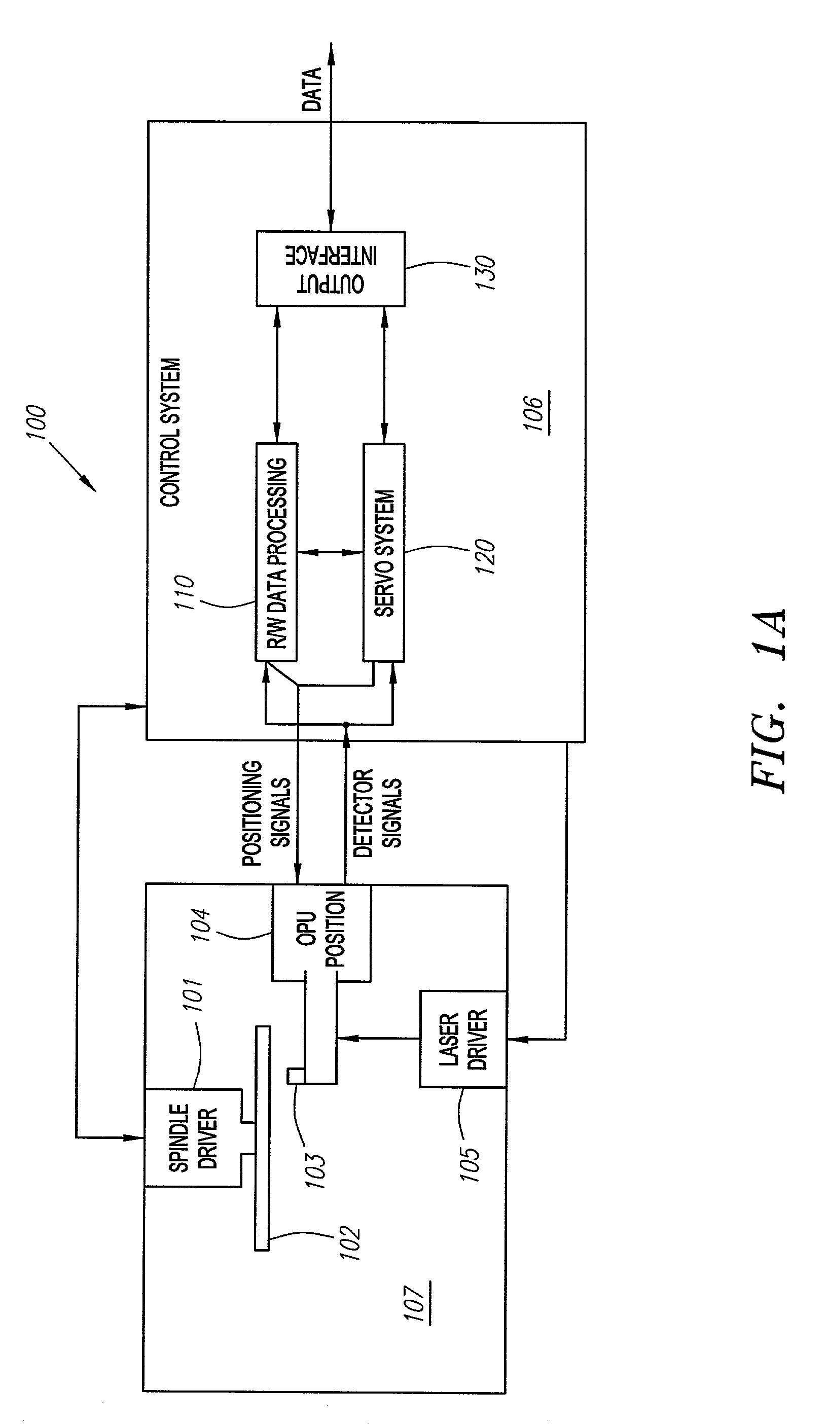
[0099]FIG. 3A shows a block diagram of an embodiment of controller 106 according to the present invention. Optical signals are received from OPU 103 (see FIGS. 2B–2D). As discussed above with FIGS. 2B, 2C and 2D, some embodiments of OPU 103 include two detectors with detector 225 including detectors 231, 232, and 233 for providing detector signals AR, ER, and CR, respectively, and detector 226 having detectors 234, 235 and 236 providing detector signals BR, FR, and DR, respectively. Further, some embodiments of OPU 103 include a laser power detector 250 mounted to receive reflected light from an annular reflector 252 positioned on periscope 210, as discussed above, and therefore provides a laser power signal LPR as well.

[0100]Detector signals received from OPU 103 are typically current signals. Therefore, the detector signals from OPU 103 are converted to voltage signals in a preamp 310. Preamp 310 includes a transimpedance amplifier, which converts cur...


PUM

PropertyMeasurementUnit
thicknessaaaaaaaaaa
diameteraaaaaaaaaa
depthaaaaaaaaaa

Abstract

A focus error signal offset calibration is presented. The focus error signal offset can be calibrated by varying the focus error signal offset to optimize an operating characteristic of the optical disk drive. In some embodiments, the operating characteristic can be a servo function. In some embodiments, the operating characteristics can be a read function.

Description

RELATED APPLICATIONS[0001]This application is related to provisional application Ser. No. 60 / 264,351, filed Jan. 25, 2001 entitled “Optical Disk Drive Servo System,” by Ron J. Kadlec, Christopher J. Turner, Hans B. Wach, and Charles R. Watt, from which this application claims priority, herein incorporated by reference in its entirety.CROSS-REFERENCE TO CD-ROM APPENDIX[0002]CD-ROM Appendix A, which is a part of the present disclosure, is a CD-ROM appendix consisting of twenty two (22) text files. CD-ROM Appendix A is a computer program listing appendix that includes a software program executable on a controller as described below. The total number of compact disks including duplicates is two. Appendix B, which is part of the present specification, contains a list of the files contained on the compact disk. The attached CD-ROM Appendix A is formatted for an IBM-PC operating a Windows operating system.[0003]A portion of the disclosure of this patent document contains material which is ...

Claims


Application Information

Patent Timeline
Patent Type & Authority Patents(United States)
IPC IPC(8): G11B7/00G11B7/09G11B7/095
CPCG11B7/0945G11B7/0908G11B7/094
Inventor KADLEC, RON J.WACH, HANS B.TURNER, CHRISTOPHER J.
Owner RPX CORP
Why Eureka
Try Eureka