Signal Processors and Methods for Estimating Transformations Between Signals with Least Squares

a signal processor and signal technology, applied in the field of signal processing, can solve the problems of distorted signals, more difficult to accurately detect, recognize or match the reference signal with its counterpart in the suspect image, and difficult to achieve the effect of accurately and efficiently computing, accurately detecting and recognizing

Active Publication Date: 2012-03-29
DIGIMARC CORP
View PDF10 Cites 92 Cited by
  • Summary
  • Abstract
  • Description
  • Claims
  • Application Information

AI Technical Summary

Benefits of technology

[0003]There are a wide variety of signal processing applications in which the affine transformation between a suspect signal and a reference signal need to be computed accurately and efficiently. This is particularly the case for signal detection and recognition applications for images, and it applies to other types of signals as well. In the case of signal detection and signal recognition, the objective for the computing device is to determine whether a particular reference signal is present in a suspect signal. This objective is more difficult when the reference signal is present, yet is distorted by a transform of the coordinate space. In image processing...

Problems solved by technology

This objective is more difficult when the reference signal is present, yet is distorted by a transform of the coordinate space.
Unless there is a means to determine and compensate for the affine transformation of the reference signal, it is more difficult to accurately detect, recognize or match the reference signal with its counterpart in the suspect image.
This signal processing problem is important to a variety of fields.
The signals captured in these devices are often distorted by transformations.
When signal transforms are computed in digital computing environments of general purpose processing units or special purpose digital logic circuits, a number of challenges arise.
Some of these challenges include the errors caused by representing signals in discrete digital logic.
Not only is quantization error intr...

Method used


Image

  • Signal Processors and Methods for Estimating Transformations Between Signals with Least Squares
  • Signal Processors and Methods for Estimating Transformations Between Signals with Least Squares
  • Signal Processors and Methods for Estimating Transformations Between Signals with Least Squares

Examples


Embodiment Construction

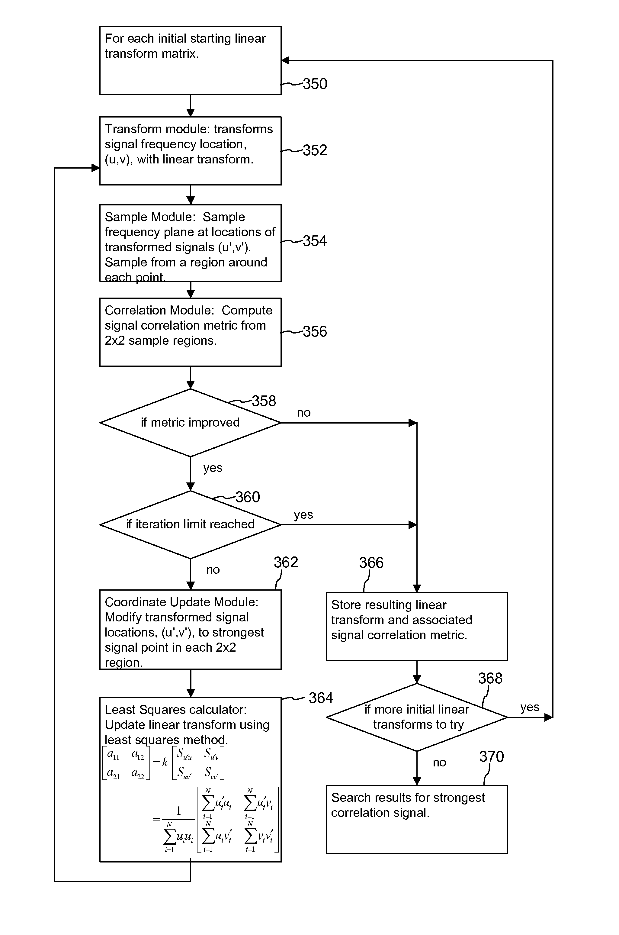
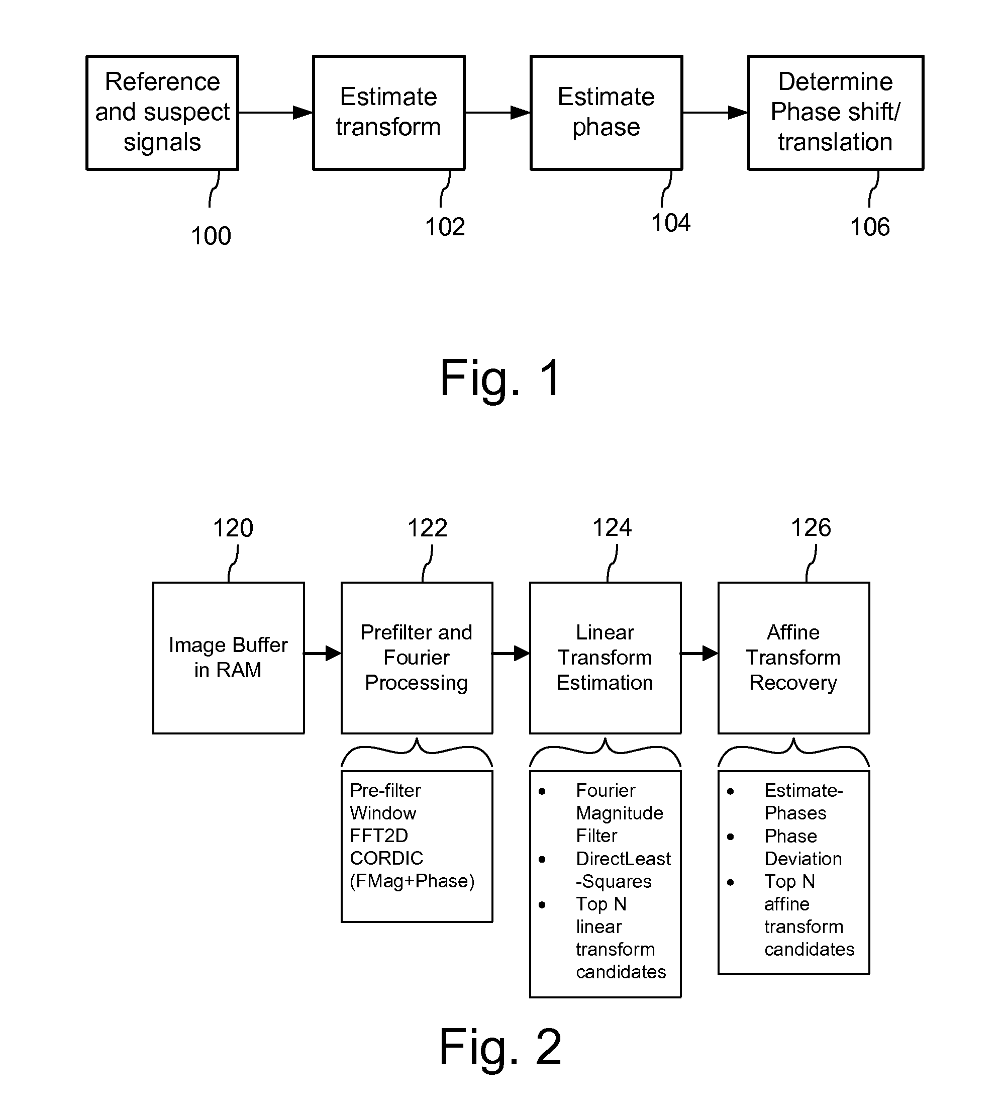
[0035]FIG. 1 is a block diagram illustrating an implementation of a process for determining a transformation between a reference and suspect signal. We refer to this process as a transformation recovery process because it recovers a transformation of the reference signal from a suspect signal captured within a device. In particular, we have implemented this method to recover the transform required to align the suspect signal with the reference signal. The process takes as input a discrete representation of a known reference and the captured suspect signal 100 and determines an estimate of a transformation, which when applied to the reference signal, would approximate the suspect signal. The transformation recovery process is sub-divided into stages 102-106 in which the first stage provides an estimate of a transform (e.g., a linear transform described by 4-D vector of linear transform parameters (or 2 by 2 linear transform matrix)) and the subsequent stages refine the estimate by fi...


PUM


Abstract

Signal processing devices and methods estimate transforms between signals using a least squares technique. From a seed set of transform candidates, a direct least squares method applies a seed transform candidate to a reference signal and then measures correlation between the transformed reference signal and a suspect signal. For each candidate, update coordinates of reference signal features are identified in the suspect signal and provided as input to a least squares method to compute an update to the transform candidate. The method iterates so long as the update of the transform provides a better correlation. At the end of the process, the method identifies a transform or set of top transforms based on a further analysis of correlation, as well as other results.

Description

RELATED APPLICATION DATA[0001]This application claims benefit of 61 / 380,180 filed Sep. 3, 2010.TECHNICAL FIELD[0002]The invention relates to signal processing, and specifically signal processing for determining transformations between signals, for use in signal detection, identification, signal matching and recognition applications, among others.BACKGROUND AND SUMMARY[0003]There are a wide variety of signal processing applications in which the affine transformation between a suspect signal and a reference signal need to be computed accurately and efficiently. This is particularly the case for signal detection and recognition applications for images, and it applies to other types of signals as well. In the case of signal detection and signal recognition, the objective for the computing device is to determine whether a particular reference signal is present in a suspect signal. This objective is more difficult when the reference signal is present, yet is distorted by a transform of th...

Claims


Application Information

Patent Timeline
IPC IPC(8): G06F17/14
CPCG06T1/0064G06T1/0021G06T3/0006G06K9/6206G06F1/02G06V10/754G06T3/0056
Inventor SHARMA, RAVI K.LORD, JOHN DOUGLASLYONS, ROBERT G.
Owner DIGIMARC CORP
Why Eureka
Try Eureka