Mold of removing chips

a technology of removing chips and molding, which is applied in the field of molding, can solve the problems of increasing production costs, reducing the normal useful life of the prior mold b>2/b>, and unable to meet the required precision requirements, so as to reduce the production cost of the product, enhance the strength of the and effectively overcome the stress concentration of the continuous upper and lower cores

Inactive Publication Date: 2012-04-05
CHENG UEI PRECISION IND CO LTD
View PDF9 Cites 0 Cited by
  • Summary
  • Abstract
  • Description
  • Claims
  • Application Information

AI Technical Summary

Benefits of technology

[0009]Based on the above description, a mold of removing chips as provided by the present invention disposes the chip-removing grooves on the upper and lower ends thereof to divide the continuous first and second forming grooves into several segments. When the mold is machining the product, the chips stacked in all segments of the first and second forming grooves can be easily removed out of the mold through the chip-removing grooves, thereby effectively overcoming the stress concentration of the continuous upper and lower cores caused by the chips blocking up the cont

Problems solved by technology

Therefore, on one hand, the normal useful life of the prior mold 2 is reduced and the production cost is increas

Method used


Image

  • Mold of removing chips
  • Mold of removing chips
  • Mold of removing chips

Examples


first embodiment

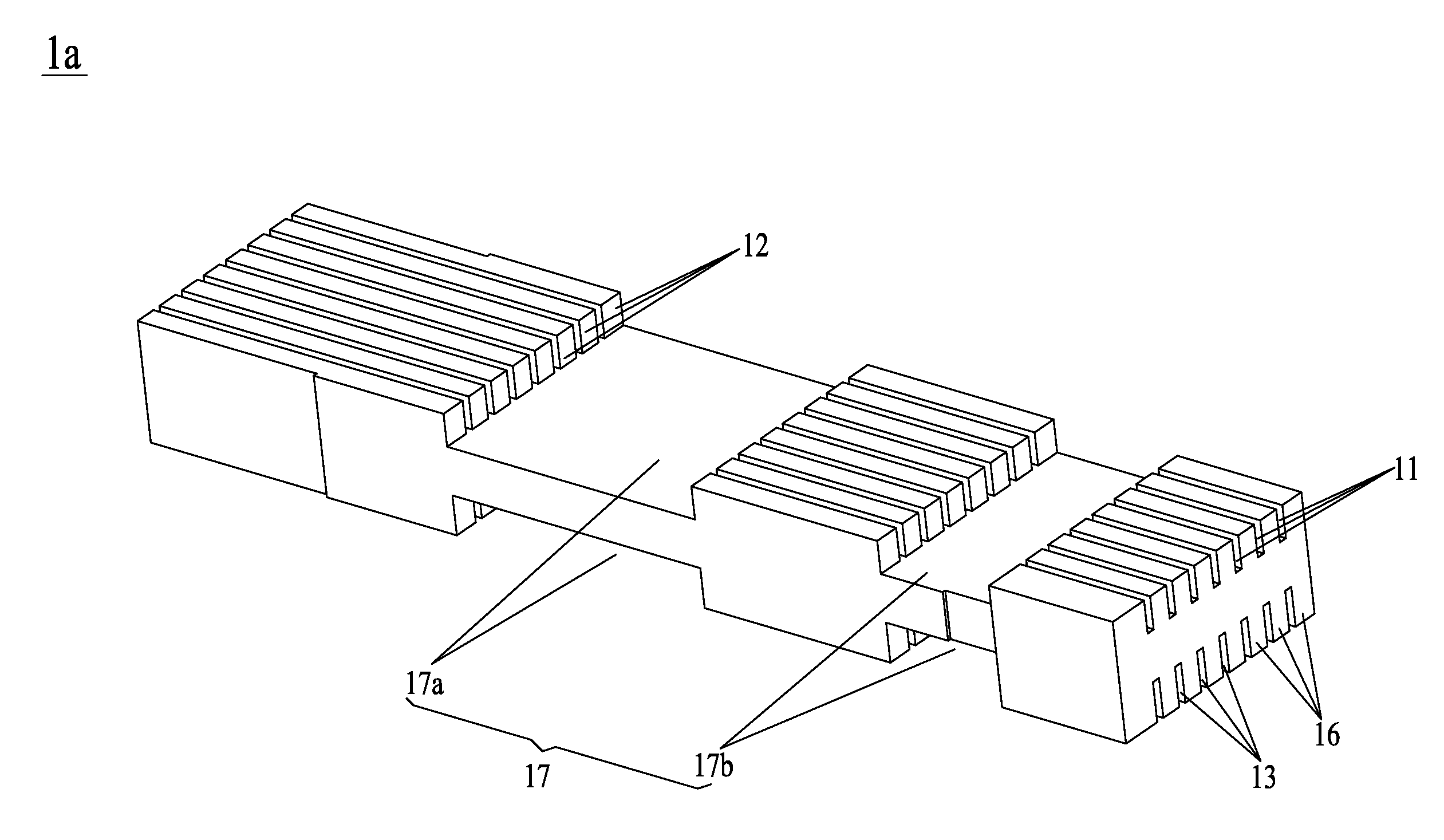
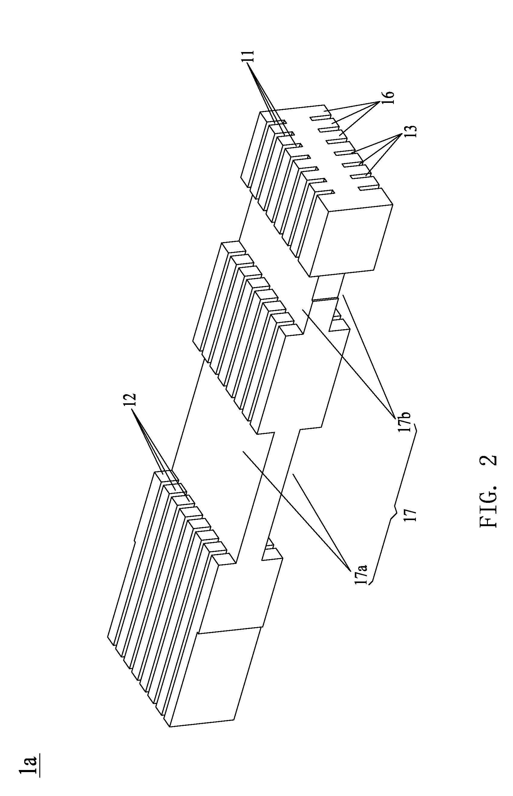
[0018]Please refer to FIG. 2, which shows a mold 1a of removing chips according to the present invention. In FIG. 2, the mold 1a of removing chips is used to machine a product having higher, smaller and thinner center pins. The mold 1a disposes a plurality of first forming grooves 11, which are parallel each other and are used to machine the profiles of the center pins, on an upper end thereof. The first forming grooves 11 are preferably arranged with equal space on the upper end of the mold 1a for satisfying the process needs. The first forming grooves 11 pass through a front surface and a back surface of the mold 1a. The upper end of the mold 1a is divided into a plurality of upper cores 12 by the first forming grooves 11. The number of the first forming grooves 11 is determined by the number of the center pins waiting to be formed, and the number of the upper cores 12 is determined by the number of the first forming grooves 11.

[0019]The mold 1a disposes a plurality of second form...

third embodiment

[0023]Please refer to FIGS. 6 and 7, which show a machining state of the mold 1c of machining the product 3 with center pins 31 on the When machining the product 3, the product is first fixed, then the mold 1c is adjusted for exactly facing to the product 3, and then the mold 1c can be driven to move along a first direction pointed by an arrow A for machining the product 3 till the center pins 31 is formed on the product 3. During machining the center pins 31 of the product 3, the chips falling into the first, second and third forming grooves 11, 13, 14 can be easily removed out of the mold 1c through the chip-removing grooves 17. Therefore, the mold 1c can improve the machining efficiency of the center pins 31 of the product 3.

[0024]As described above, the mold 1a of the present invention disposes the chip-removing grooves 17 on the upper and lower ends thereof to divide the continuous first and second forming grooves 11, 13 into several segments. When the mold 1c is machining the...


PUM

PropertyMeasurementUnit
Strengthaaaaaaaaaa

Abstract

Provided is a mold of removing chips for machining a product with center pins. The mold includes a plurality of first forming grooves disposed on an upper end thereof, a plurality of second forming grooves disposed on a lower end thereof, and at least two chip-removing grooves separately disposed on the upper and lower ends thereof. The first and second forming grooves separately divide the upper and lower ends into a plurality of upper and lower cores. The chip-removing grooves are separately cutting the first and second forming grooves. The chip-removing grooves can make the chips be easily removed out of the mold for preventing the chips from blocking up the first and second forming grooves and avoiding the deformation of the upper and lower cores, thereby enhancing the strength of the mold, elongating the useful life thereof and ensuring the machining precision of the product.

Description

BACKGROUND OF THE INVENTION[0001]1. Field of the Invention[0002]The present invention relates to a mold for machining a product with center pins, and more particularly to a mold of removing chips, which is used to machine a product with center pins.[0003]2. Description of the Prior Art[0004]At present, a product with center pins has been widely used in the market. The center pins of the product has higher, smaller and thinner features, so that the mold for machining the center pins needs to have forming grooves corresponding to the center pins. The prior mold for machining the center pins is described as follows.[0005]Please refer to FIG. 1, the prior mold 2 for machining the center pins disposes a plurality of first forming grooves 21, which are parallel each other and are used to machine the profiles of the center pins, on an upper end thereof. The first forming grooves 21 are passing through a front surface and a back surface of the mold 2, and the upper end of the mold 2 is divi...

Claims


Application Information

Patent Timeline
IPC IPC(8): B26D7/06
CPCB23D13/00B23D11/00Y10T83/202
Inventor WU, XIAO-PINGHO, SHIH-HSIUNGCHIANG, KUN-HSUEH
Owner CHENG UEI PRECISION IND CO LTD
Why Eureka
Try Eureka