Liquid ejecting apparatus

Active Publication Date: 2012-04-05
SEIKO EPSON CORP
View PDF1 Cites 8 Cited by
  • Summary
  • Abstract
  • Description
  • Claims
  • Application Information

AI Technical Summary

Benefits of technology

[0012]It is preferable that the slight-vibration pulse include a first holding component (for example, a first holding component Wh1) which connects the first changing component with the second changing component and in which a potential of an end of the first changing component is held. It is preferable that, for a Helmholtz resonance period of TC in the pressure chamber, a total time (for example, a total time LA) which is a sum of a time length (for example, a time length Th1) of the first holding component and a time length (for example, a time length Tv2) of the second changing component be set to be equal to or longer than 3TC/4 and equal to or shorter than 5TC/4. In this aspect, because the total time that is a sum of the time length of the first holding component and the time length of the second changing component is set to be equal to or longer than 3TC/4 and equal to or shorter than 5TC/4, a pressure variation (for example, a pressure variation X1) generated in the pressure chamber by supplying the first changing component is immediately reduced by supplying the second changing component. Consequently, malfunctions caused by continuation of a pressure variation in the pressure chamber (for example, accidental ejection of the liquid, pulling of air bubbles into the pressure chamber, and an error in an amount of ejected liquid) can be prevented. It is preferable that the total time which is a sum of the time length of the first holding component and the time length of the second changing component be set to be equal to or longer than 7TC/8 and equal to or shorter than 9TC/8, so that an effect of reducing the pressure variation caused by the first changing component by supplying the second changing component becomes further prominent. It is preferable that the total time which is a sum of the time length of the first holding component and the time length of the second changing component be set to be TC, so that the effect becomes very prominent.
[0

Problems solved by technology

However, in a case in which the amplitude of the slight-vibration pulse shown in FIG. 10 or FIG. 11 is increased, there is a high probability that liquid will be accidentally eject

Method used


Image

  • Liquid ejecting apparatus
  • Liquid ejecting apparatus
  • Liquid ejecting apparatus

Examples


first embodiment

A. First Embodiment

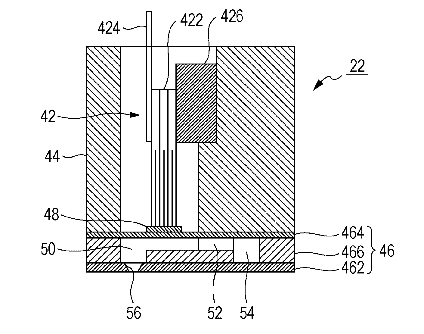
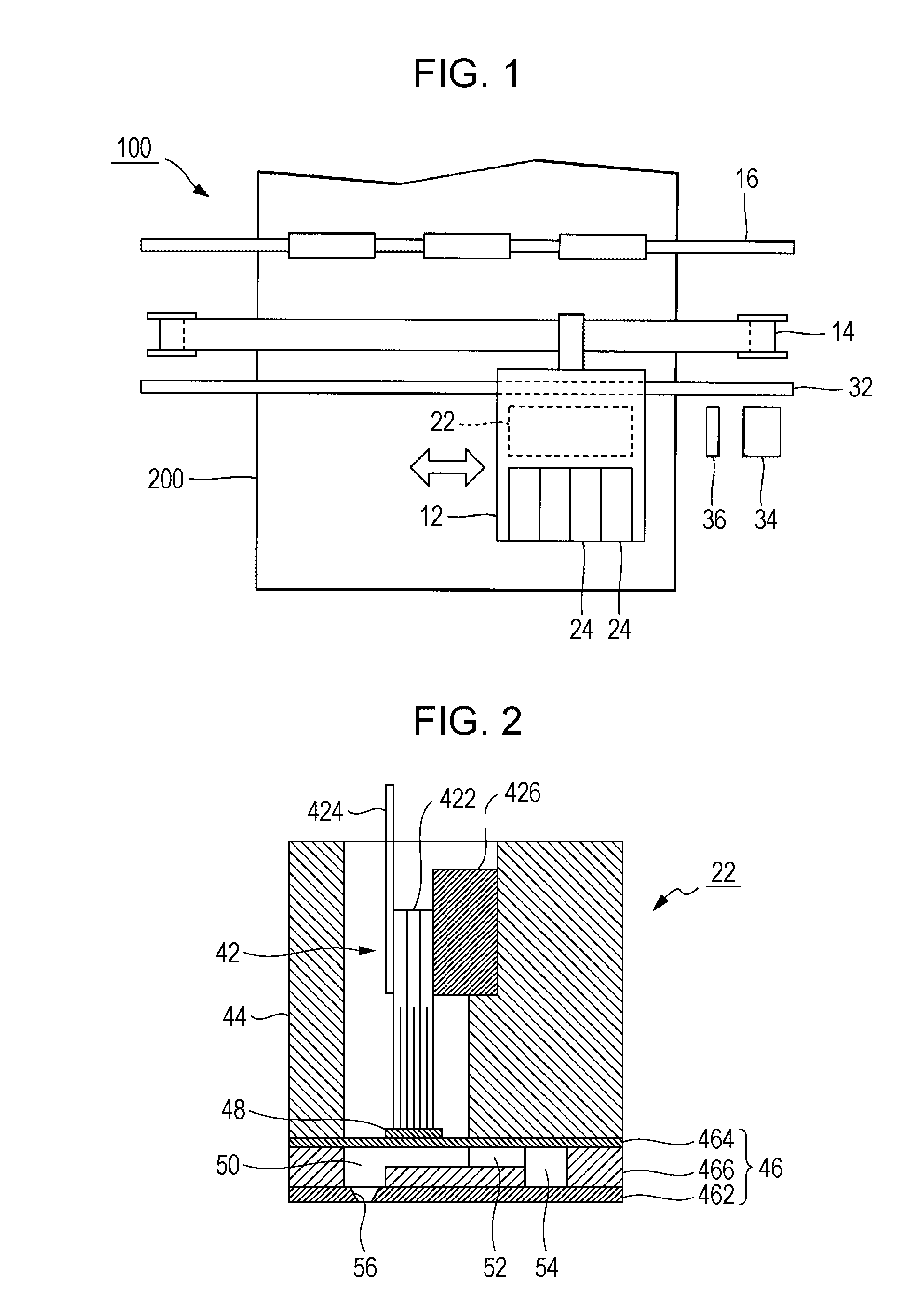
[0026]FIG. 1 is a partial schematic view of an ink-jet printing apparatus 100 according to a first embodiment of the invention. The printing apparatus 100 is a liquid ejecting apparatus that ejects tiny ink droplets onto a recording sheet 200, and is configured so as to include a carriage 12, a moving mechanism 14, and a sheet transporting mechanism 16. A recording head 22 that functions as a liquid discharging unit is placed in the carriage 12, and ink cartridges 24 that store ink to be supplied to the recording head 22 are mounted so as to be detachably attached. Alternatively, a configuration may be employed in which the ink cartridges 24 are fixed to a housing (not shown) of the printing apparatus 100 so as to supply ink to the recording head 22.

[0027]The moving mechanism 14 causes the carriage 12 to reciprocate along a guide shaft 32 in the main scanning direction (the width direction of the recording sheet 200, as indicated by the arrow in FIG. 1). The posit...

second embodiment

B. Second Embodiment

[0046]A second embodiment of the invention will be described below. Components which are provided in each embodiment that is described below as an example and whose functions and effects are equivalent to the functions and effects thereof in the first embodiment are denoted by the same reference numerals used in the above description, and a detailed description thereof will be omitted as appropriate.

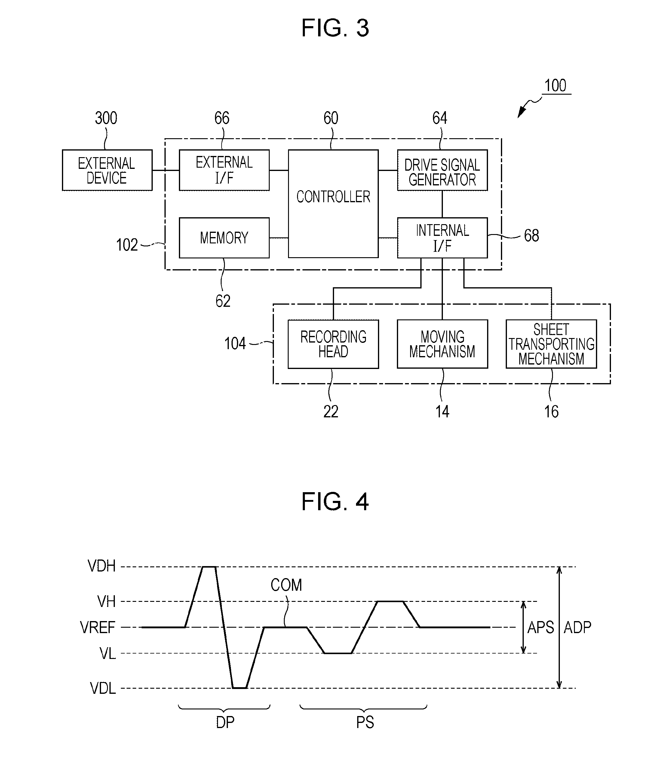
[0047]When the pressure in the pressure chamber 50 is increased by supplying the first changing component Wv1, a periodic pressure variation in the pressure chamber 50 continues even after a vibration of the piezoelectric vibrator 422 (the vibration plate 48) has been stopped by supplying the first holding component Wh1. However, if the pressure variation in the pressure chamber 50 continues for a long time period, there is a high probability that, because of an influence of, for example, interference with a vibration generated from another portion of the pressure cha...

modification examples

C. Modification Examples

[0064]The embodiments described above can be variously modified. Specific modification examples are provided below. Any two or more modification examples selected from the modification examples provided below may be combined as appropriate.


PUM


Abstract

A piezoelectric vibrator varies the pressure in a pressure chamber in accordance with a drive signal, whereby ink contained in the pressure chamber is ejected from a nozzle. The drive signal includes a slight-vibration pulse used to change the pressure in the pressure chamber to an extent that the ink is not ejected. The slight-vibration pulse includes a first changing component in which the potential changes from a reference potential in a negative direction in which the pressure in the pressure chamber is increased by the piezoelectric vibrator, a second changing component which is generated to follow the first changing component and in which the potential changes so as to cross the reference potential in a positive direction, and a third changing component which is generated to follow the second changing component and in which the potential changes to the reference potential in the negative direction.

Description

BACKGROUND[0001]1. Technical Field[0002]The present invention relates to techniques for ejecting liquid, such as ink.[0003]2. Related Art[0004]Hitherto, liquid ejection techniques have been proposed, in which liquid (e.g., ink) contained in a pressure chamber is ejected from a nozzle by changing the pressure in the pressure chamber using a pressure generating element, such as a piezoelectric vibrator or a heating element. In the liquid ejection techniques, a configuration is employed, in which, from the viewpoint of realization of stable ejection by reducing an increase in the viscosity of liquid contained in a pressure chamber, the liquid is appropriately stirred by providing a slight vibration to an extent that the liquid is not ejected. A slight vibration is generated in the pressure chamber by supplying a slight-vibration pulse to a pressure generating element.[0005]JP-A-2002-113858 discloses a slight-vibration pulse QA having a waveform shown in FIG. 10. The slight-vibration pu...

Claims


Application Information

Patent Timeline
IPC IPC(8): B41J29/38
CPCB41J2/0458B41J2/04596B41J2/04588B41J2/04581
Inventor YAMASHITA, NORIAKI
Owner SEIKO EPSON CORP
Why Eureka
Try Eureka