Laser speckle reduction element

Active Publication Date: 2012-04-05
PANASONIC CORP
View PDF4 Cites 116 Cited by
  • Summary
  • Abstract
  • Description
  • Claims
  • Application Information

AI Technical Summary

Benefits of technology

[0008]The present invention further relates to a method for reducing a coherence of a coherent light beam. The method includes generating a coherent light beam by a pulsed operation of a laser source with a pulse duration to broaden a wavelength bandwidth of the coherent light beam, where the pulsed operation reduces a coherence of the coherent light beam. The method also includes collimating the coherent light beam to produce a collimated light beam and passing the collimated light beam through a transparent despeckle e

Problems solved by technology

Because they emit coherent light, lasers may be prone to speckle.
Speckle patterns may severely degrade the image quality

Method used


Image

  • Laser speckle reduction element
  • Laser speckle reduction element
  • Laser speckle reduction element

Examples


Embodiment Construction

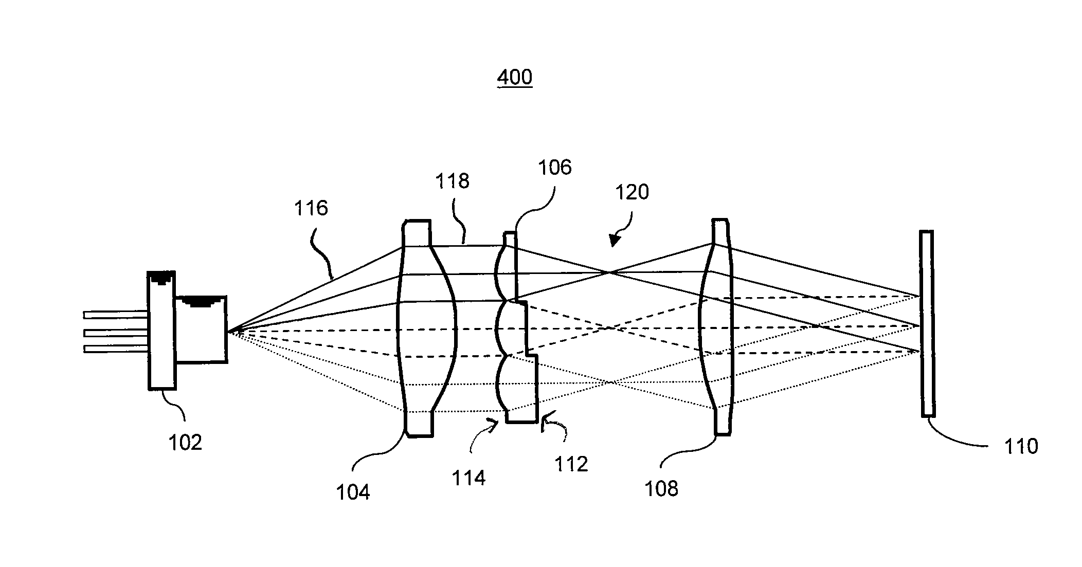
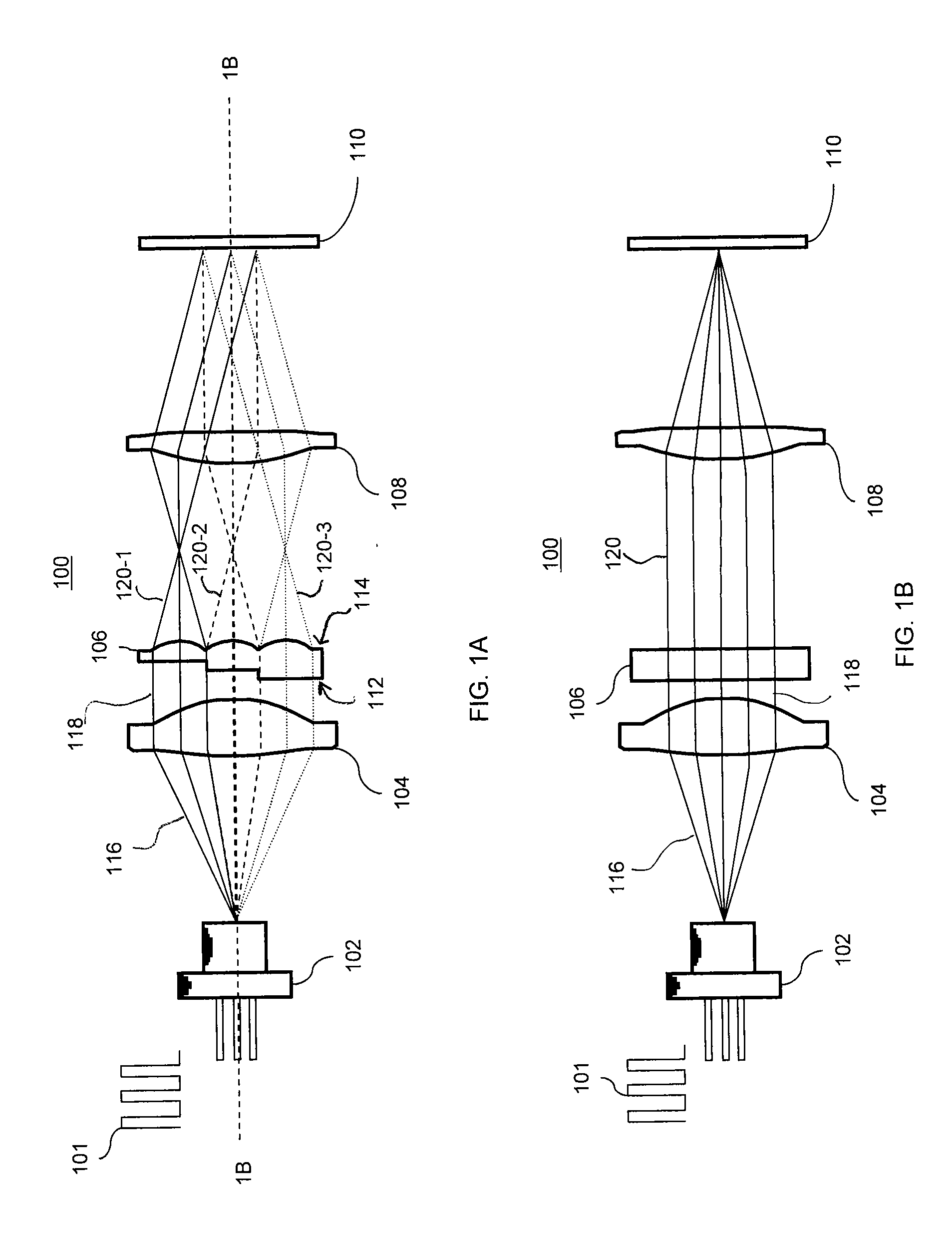
[0031]For light of high or moderate coherence, conventional speckle reduction typically involves generating many independent speckle patterns that may average each other out at the image plane. In general, speckle reduction methods may be categorized as belonging to one of dynamic reduction methods and static reduction methods.

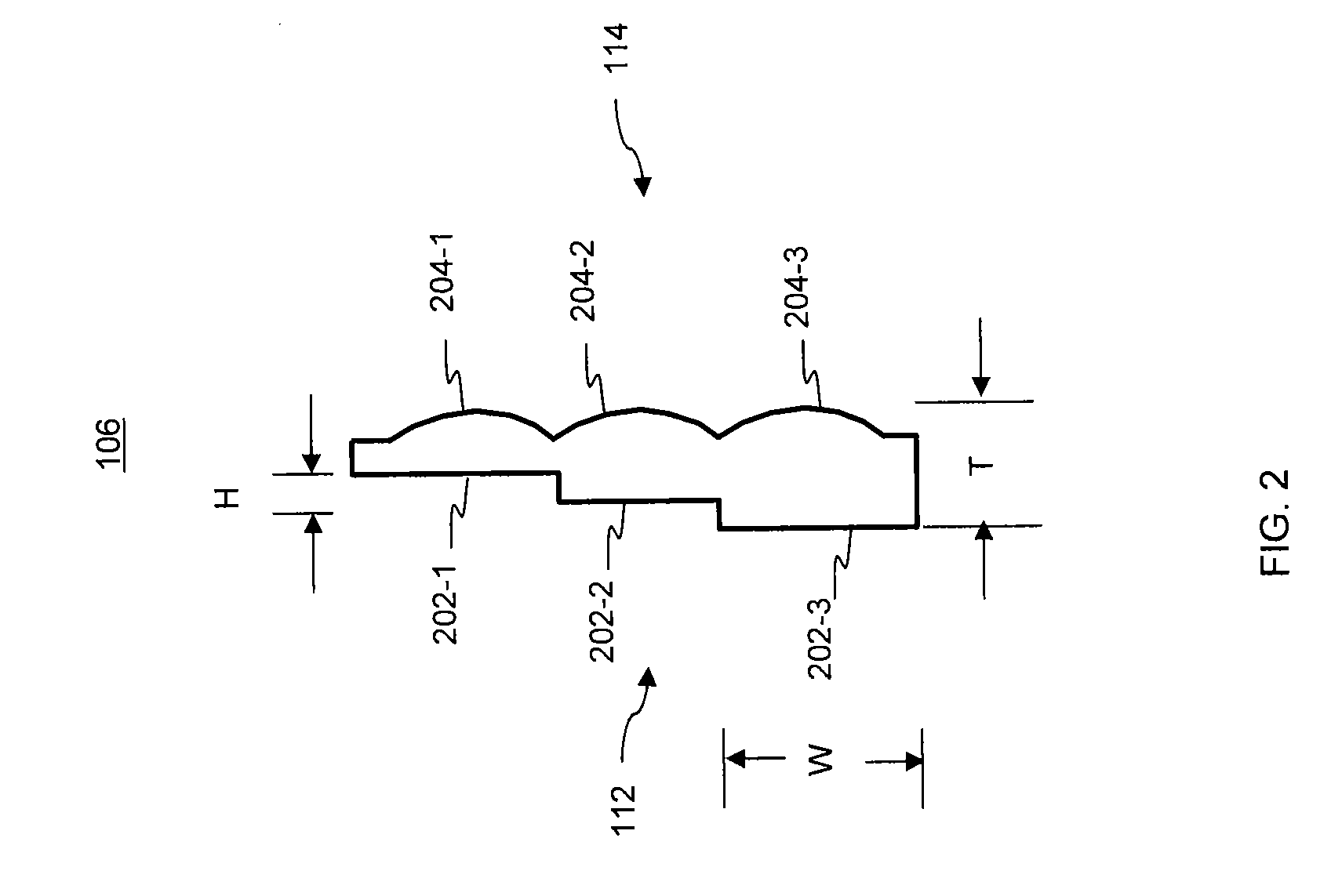
[0032]Dynamic reduction methods typically involve the use of a time-varying component. For example, vibration of a laser fiber or screen, rotation of a diffuser, random shuttering of a light valve and variation of polarization states with time. Static reduction methods typically involve the use of stationary components. For example, stationary diffusers and stationary optical path difference elements such as an optical fiber bundle in which each of the individual optical fibers have different lengths.

[0033]Dynamic reduction methods typically outperform static reduction methods, because the dynamic reduction methods can more effectively average the speckle patt...


PUM


Abstract

Despeckle elements, laser beam homogenizers and methods for despeckling are provided. The despeckle element includes a transparent material having a first surface including a plural number of optical steps and a second surface having a plural number of microlenses. Each of the number of optical steps is in a one-to-one correspondence with at least one of the microlenses. One of the first surface and the second surface is configured to receive collimated light having a coherence length and a remaining one of the first surface and the second surface is configured to pass the collimated light separated into a plurality of beamlets corresponding to the number of microlenses. A height of each step of at least two of the optical steps is configured to produce an optical path difference of the collimated light longer than the coherence length.

Description

CROSS REFERENCE TO RELATED APPLICATIONS[0001]The application is related to and claims the benefit of U.S. Provisional Application No. 61 / 388,238 entitled LASER SPECKLE REDUCTION ELEMENT filed on Sep. 30, 2010, the contents of which are incorporated herein by reference.FIELD OF INVENTION[0002]The present invention relates to laser illumination and laser displays and, more particularly, to despeckle elements, laser beam homogenizers, despeckling laser arrays and methods of reducing speckle in coherent light sources.BACKGROUND OF THE INVENTION[0003]Lasers are known, and find application in a wide variety of fields, such as consumer products, medical devices, metrology, and industrial equipment for fabrication, cutting, dicing, heating and annealing. In general, a laser is an optical source that emits a coherent light beam (also referred to herein as coherent light). The coherent light may be emitted as a relatively narrow beam and may be focused to very small spots.[0004]Because they e...

Claims


Application Information

Patent Timeline
IPC IPC(8): G02B27/48G02B27/28G02B27/12
CPCG02B27/48G02B27/286
Inventor MIZUYAMA, YOSUKELETO, RICCARDO
Owner PANASONIC CORP
Why Eureka
Try Eureka