Apparatus and method for controlling a wireless feeder network

a wireless feeder and antenna technology, applied in the field of antennas and methods for controlling a wireless feeder network, can solve the problems of increasing the cost of providing, significantly increasing the cost to the operator, and clearly increasing the cost, so as to achieve the effect of improving spectral efficiency and improving spectral efficiency

Active Publication Date: 2012-04-05
AIRSPAN IP HOLDCO LLC
View PDF1 Cites 16 Cited by
  • Summary
  • Abstract
  • Description
  • Claims
  • Application Information

AI Technical Summary

Benefits of technology

[0035]In one embodiment, the feeder base stations and feeder terminals are at fixed locations. This enables significant improvements in spectral efficiency, since the communications taking place over the feeder link do not have to take account of factors that would occur when one or both of the feeder base stations and feeder terminals were mobile.
[0036]The traffic reports received at said step (iii) can take a variety of forms. In one embodiment, those traffic reports are indicativ

Problems solved by technology

However, as the number of access base stations are increased, this increases the cost of providing the earlier-described wired or wireless point-to-point backhaul connections between the various access base stations and the communications network.
This significantly increases the cost to the operator.
For wired backhaul, the cost clearly increases as each additional backhaul connection is required.
For a wireless backhaul solution, there is a similar increase in the cost, since scarce radio frequencies must be al

Method used


Image

  • Apparatus and method for controlling a wireless feeder network
  • Apparatus and method for controlling a wireless feeder network
  • Apparatus and method for controlling a wireless feeder network

Examples


Embodiment Construction

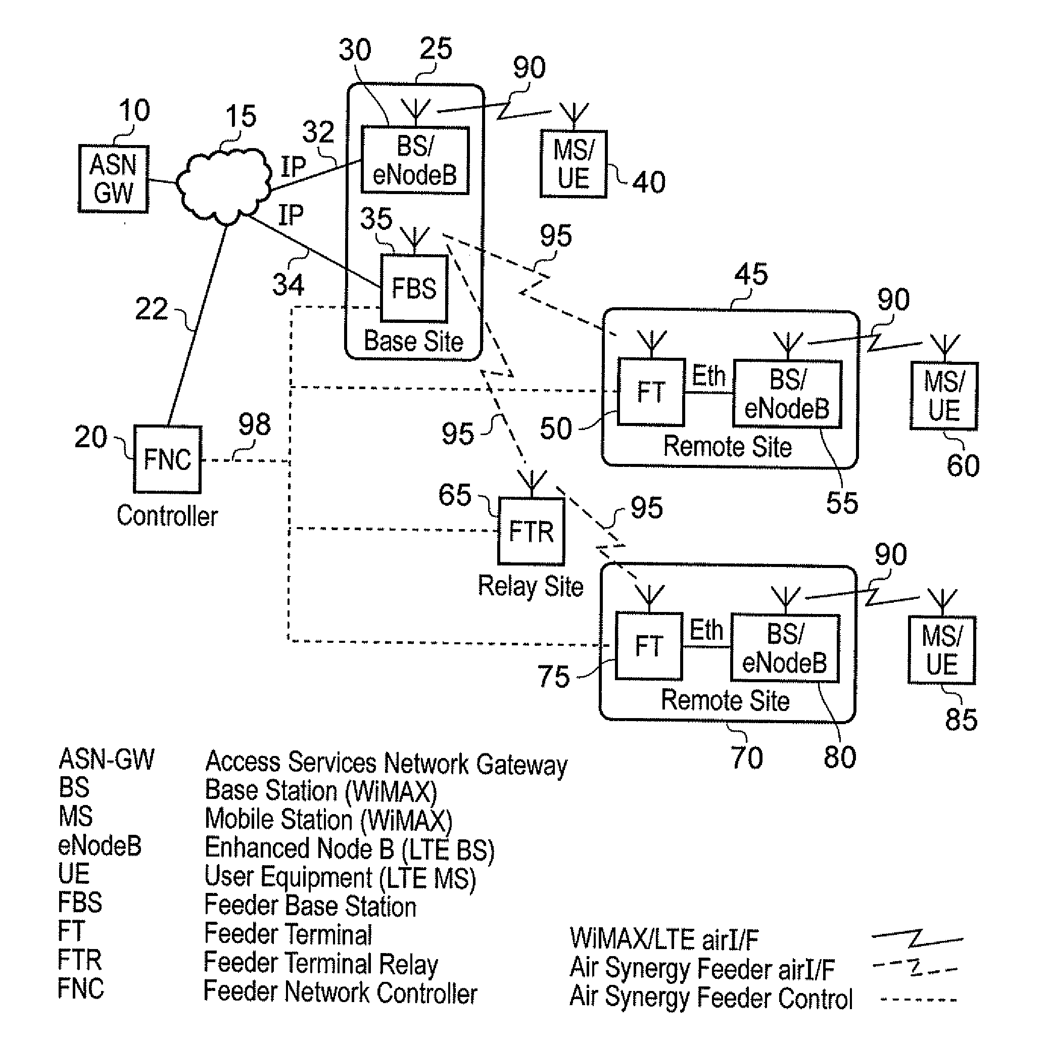
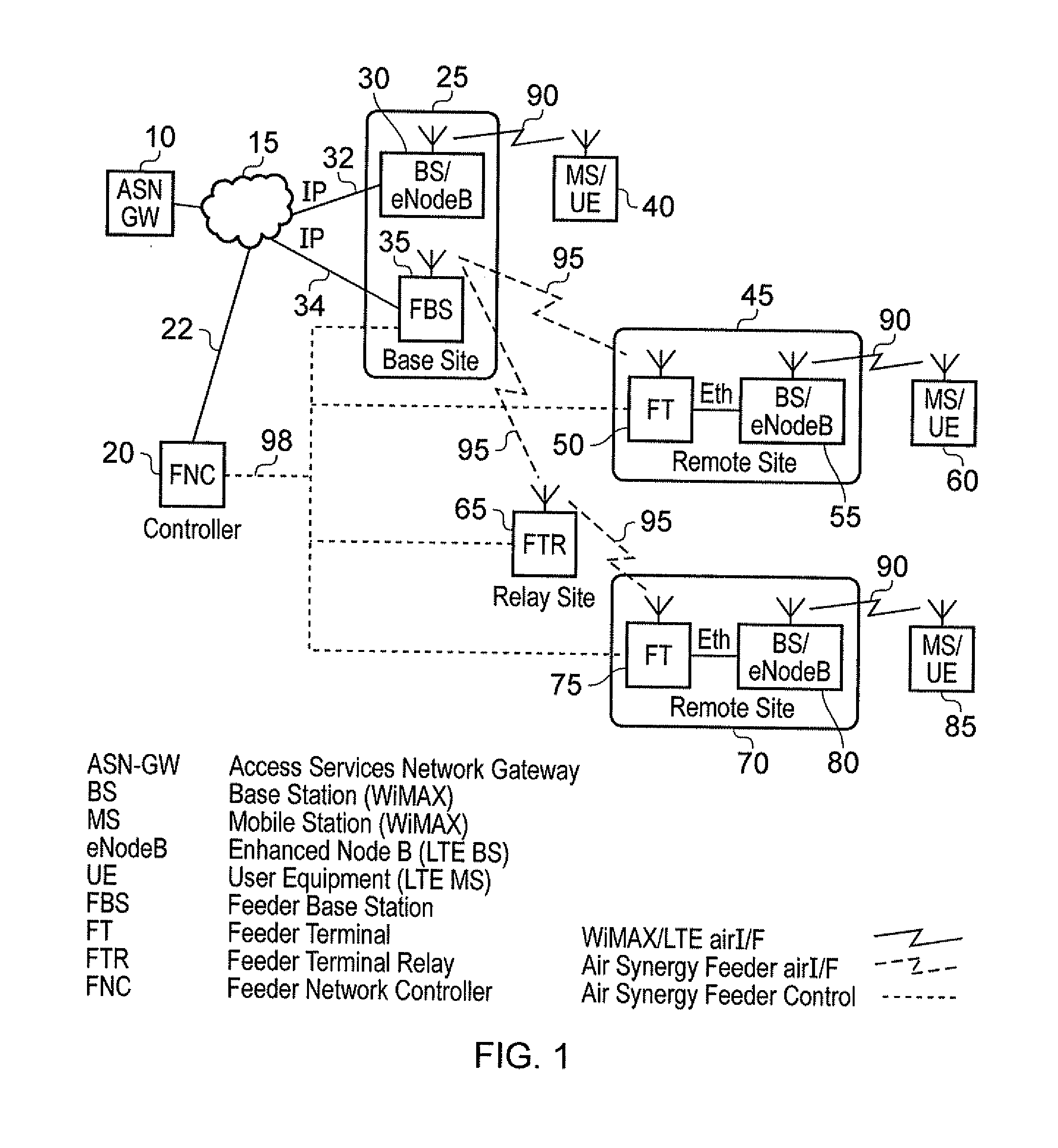
[0084]FIG. 1 is a block diagram schematically illustrating a network architecture including a wireless feeder network in accordance with one embodiment. As shown in FIG. 1, a number of access base stations 30, 55, 80 are provided in the conventional manner to communicate via a wireless air interface 90 with a number of mobile stations / items of end user equipment 40, 60, 85. Whilst for simplicity, each base station 30, 55, 80 is shown as communicating with a single item of end user equipment, it will be appreciated that in practice such base stations form point-to-multipoint devices enabling a plurality of items of end user equipment to communicate with an individual base station. The items of end user equipment may be mobile or fixed, and any one of a number of known wireless communication protocols may be used to effect the wireless links 90. For example, in one embodiment such wireless links may be constructed using WiMAX or LTE air interfaces.

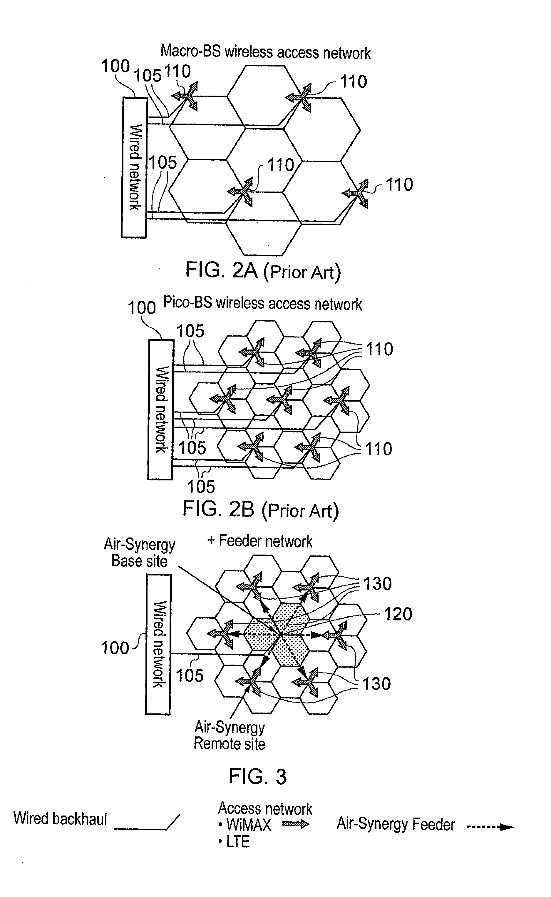
[0085]The access network consisting o...


PUM


Abstract

An apparatus and method are provided for controlling a wireless feeder network used to couple access base stations of an access network with a communications network. The wireless feeder network comprises a plurality of feeder base stations coupled to the communications network and a plurality of feeder terminals coupled to associated access base stations. Each feeder terminal has a feeder link with a feeder base station, and the feeder links are established over a wireless resource comprising a plurality of resource blocks. Sounding data obtained from the wireless feeder network is used to compute an initial global schedule to allocate to each feeder link at least one resource block, and the global schedule is distributed whereafter the wireless feeder network operates in accordance with the currently distributed global schedule to pass traffic between the communications network and the access base stations. Using traffic reports received during use, an evolutionary algorithm is applied to modify the global schedule, with the resultant updated global schedule then being distributed for use. This enables the allocation of resource blocks to individual feeder links to be varied over time taking account of traffic within the wireless feeder network, thereby improving spectral efficiency.

Description

BACKGROUND OF THE INVENTION[0001]1. Field of the Invention[0002]The present invention relates to an apparatus and method for controlling a wireless feeder network used to couple access base stations of an access network with a communications network.[0003]2. Description of the Prior Art[0004]Typical access networks provide a plurality of access base stations which communicate via wireless links with mobile or fixed end user equipment. A number of wireless communications protocols are known for the communications between the access base stations and the end user equipment, for example WiFi, WiMAX, or LTE wireless communications, etc.[0005]The various access base stations need to be coupled with a communications network to allow traffic originating from the user equipment to be propagated on to the communications network, and for traffic within the communications network to be delivered to the required end user equipment within the access network. One known way to provide such connect...

Claims


Application Information

Patent Timeline
IPC IPC(8): H04W72/04H04L12/26H04W24/00H04W74/04
CPCH04W16/04H04W24/02H04W92/045H04W88/085H04W84/047H04W88/04H04W92/20
Inventor LYSEJKO, MARTINLOGOTHETIS, ANDREW
Owner AIRSPAN IP HOLDCO LLC
Why Eureka
Try Eureka