Method for installing heat shielding on a fixed internal structure of a jet engine nacelle

Inactive Publication Date: 2012-04-05
AIRCELLE
View PDF8 Cites 22 Cited by
  • Summary
  • Abstract
  • Description
  • Claims
  • Application Information

AI Technical Summary

Benefits of technology

[0014]Thanks to such a method, it is not necessary to use fixing means to keep the heat shielding in position on the IFS, despite the high temperatures that can cause the pieces to come apart following local expansions. Consequently, it suffices to coat the surfaces to be put in contact for adhesion and to adjust them relative to one another, the adhesive withstanding high temperatures and the flatness of the ply made up of the structural material enabling the safe holding of the heat shielding on the IFS. The setting

Problems solved by technology

The placement of heat shields on the IFS with this type of fixing is lengthy (several dozens of hours), given that a significant number of repetitive operations are necessary.
On the other hand, the known heat shields are not adapted for the heat shielding of the composite IFSs comprising carbon/epoxy skins, given that these heat shields of the prior art do not make it possible to locally guarantee that the temperature is kept at a value of less than or equa

Method used


Image

  • Method for installing heat shielding on a fixed internal structure of a jet engine nacelle
  • Method for installing heat shielding on a fixed internal structure of a jet engine nacelle
  • Method for installing heat shielding on a fixed internal structure of a jet engine nacelle

Examples


Embodiment Construction

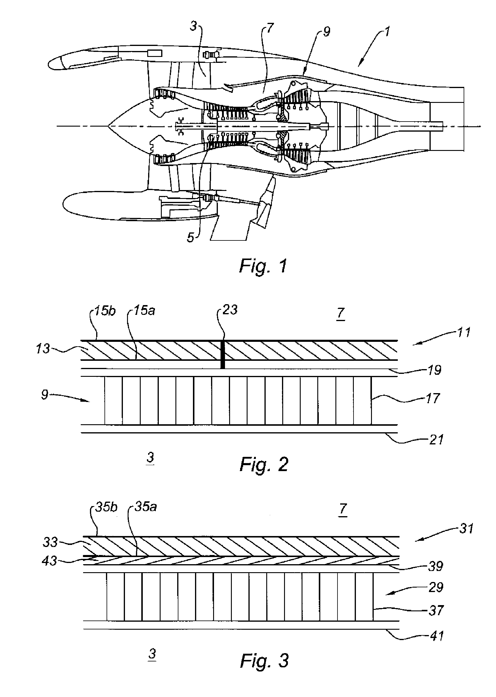
[0033]FIG. 1 shows a jet engine nacelle 1, seen in longitudinal cross-section, comprising a stream 3 in which the cold air circulates when the jet engine is operating, and a combustion chamber 5 partially surrounded by a core compartment 7 delimited on its outer portion on the stream side 3, by an inner fixed structure (IFS) 9.

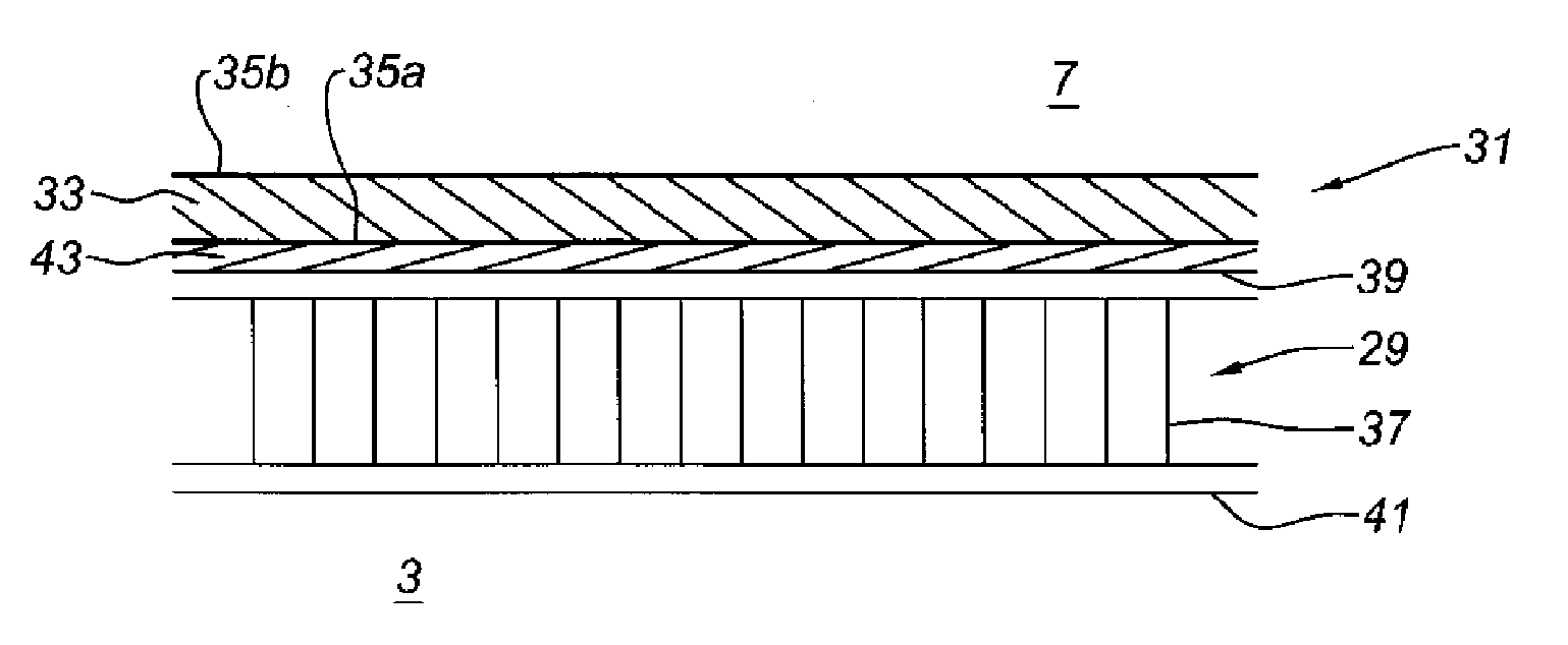
[0034]FIG. 2 shows a heat shielding 11 fixed on the core compartment side 7 on the IFS 9. The heat shielding 11 comprises a heat cushion 13, like those used for heat shields of the structure of the Airbus A380, held between two stainless steel sheets 15a and 15b. The IFS 9 comprises a metal panel 17, of the honeycomb sandwich (NIDA) type, held between an inner skin 19 and an outer skin 21, which can be made from metal or a composite material.

[0035]The heat shielding 11 is fixed using a method known in the state of the art on the inner skin 19 of the IFS, using fixing means 23. Such fixing means 23 are distributed over a large number of fastening points on the ...


PUM

PropertyMeasurementUnit
Temperatureaaaaaaaaaa
Mechanical strengthaaaaaaaaaa
Adhesivityaaaaaaaaaa

Abstract

The invention relates to a method for installing heat shielding (31), including a heat cushion (33) covered with a ply (35a) made from a structural material, on a fixed internal structure (29) of a jet engine nacelle, including the following consecutive steps: spreading an adhesive (43) that guarantees good mechanical strength at high temperatures on at least one of the elements selected from said ply (35a) and an internal skin (39) of the fixed internal structure; applying said ply (35a) to said internal skin (39); and, if necessary, setting said adhesive (43).

Description

TECHNICAL FIELD[0001]The present invention relates to a method for installing a heat shielding on a fixed internal structure of a jet engine nacelle.BRIEF DESCRIPTION OF RELATED ART[0002]An airplane is moved by one or more jet engines each housed in a nacelle.[0003]A nacelle generally has a tubular structure comprising an air intake upstream of the jet engine, an intermediate assembly intended to surround a fan of the jet engine, a rear assembly that can incorporate thrust reversing means and intended to surround the combustion chamber and all or some of the compressor and turbine stages of the jet engine, and generally ends with a jet nozzle whereof the outlet is situated downstream of the jet engine.[0004]Modern nacelles are intended to house a dual-flow jet engine that can create, on the one hand, a hot air flow (also called primary flow) coming from the combustion chamber of the jet engine, and circulating in a space delimited by a compartment having a substantially tubular shap...

Claims


Application Information

Patent Timeline
IPC IPC(8): B32B37/12B32B1/08B32B37/02
CPCF02C7/24F02K1/822F16L59/026F16L59/123Y02T50/67Y02T50/672Y10T428/13F05D2230/60F05D2230/23F05D2300/601F05D2300/2102Y10T156/10Y02T50/675Y02T50/60
Inventor LEMAINS, LAURENCEMER, PASCAL
Owner AIRCELLE
Why Eureka
Try Eureka