
Reference sensor for CPR feedback device

a technology of a reference sensor and a feedback device, which is applied in the field of medical devices, can solve the problems of reducing the amount of blood pumped to the various parts of the body, irregular heart beating, and not at all, and achieves the effect of correcting any errors in treatment and facilitating the application of cpr

Active Publication Date: 2012-04-05
PHYSIO CONTROL INC
View PDF10 Cites 78 Cited by
  • Summary
  • Abstract
  • Description
  • Claims
  • Application Information

AI Technical Summary

Benefits of technology

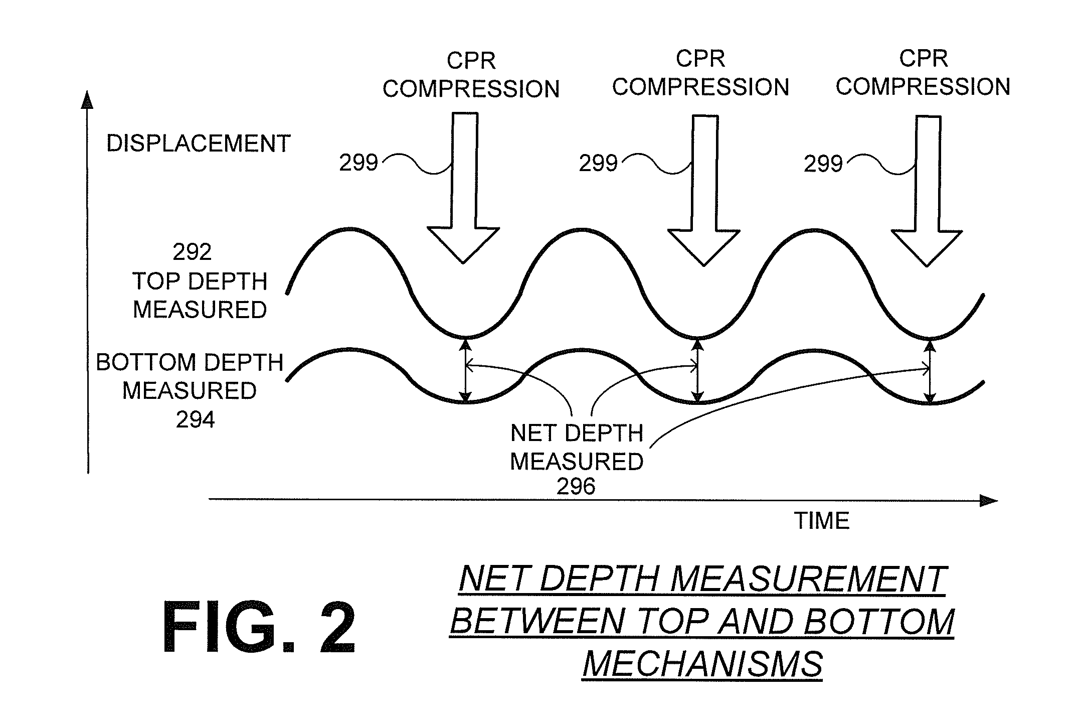
[0020]An advantage over the prior art is that the medical devices discussed in this description include features that provide the net depth of chest compressions delivered to a patient during CPR. By accurately gauging the net depths of these compressions, the medical device may provide feedback to a care giver so as to make the application of the CPR more effective and / or to correct any errors in treatment. In addition, the net depth measurements may be recorded and to be used as a diagnostic reference later.

Problems solved by technology

Sometimes, however, the electrical control system of the heart malfunctions, which can cause the heart to beat irregularly, or not at all.
Some types of arrhythmia may result in inadequate blood flow, thus reducing the amount of blood pumped to the various parts of the body.
In a SCA, the heart fails to pump blood effectively, and, if not treated, death can occur.
In fact, it is estimated that SCA results in more than 250,000 deaths per year in the United States alone.
When that happens, the heart does not pump enough blood to deliver enough oxygen to the vital organs.
A challenge with defibrillation is that the electrical shock must be administered very soon after the onset of VF.
Regardless, VF can occur unpredictably, even to a person who is not considered at risk.
This feedback can be difficult to provide because CPR is administered on a variety of surfaces, all with different amounts of flex or give.
This surface differentiation can make compression depth measurements difficult to estimate.

Method used


Image

  • Reference sensor for CPR feedback device
  • Reference sensor for CPR feedback device
  • Reference sensor for CPR feedback device

Examples


Embodiment Construction

[0030]As has been mentioned, the present description is about medical devices, control systems, software and methods for measuring the depth of Cardio Pulmonary Resuscitation (CPR) chest compressions delivered to the chest of a patient.

[0031]Embodiments are now described in more detail.

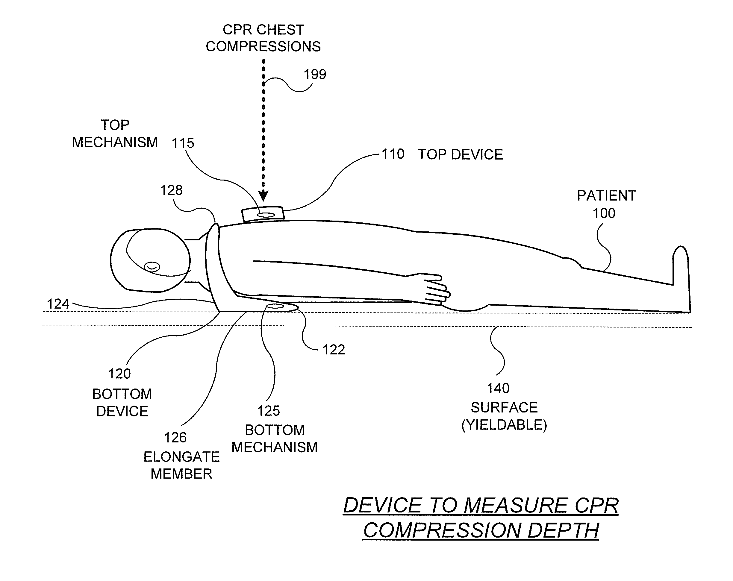
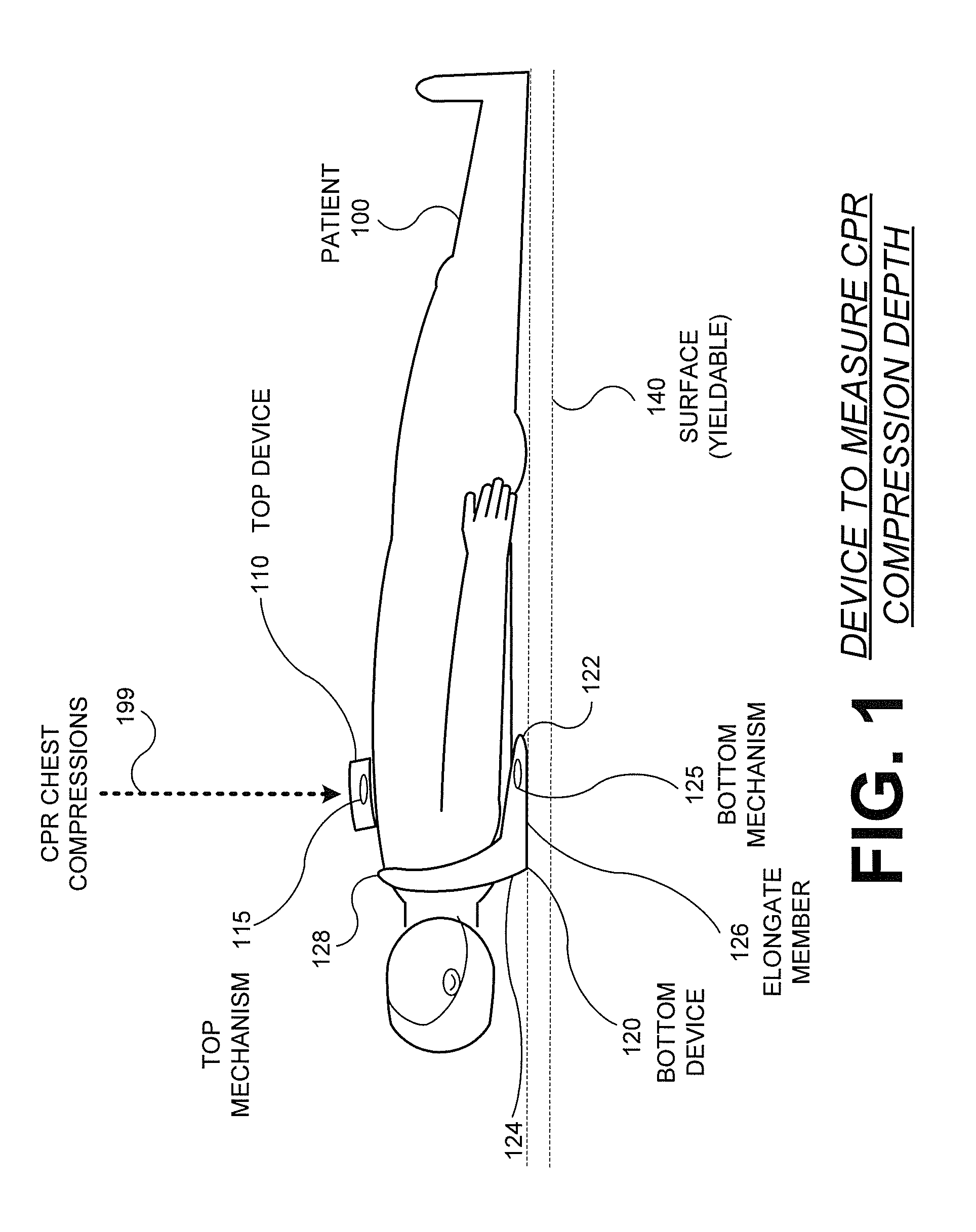
[0032]FIG. 1 is a diagram of a cooperating pair of medical devices structured to measure CPR compression depth according to embodiments. The pair of medical devices includes a top device 110 and a bottom device 120 that work cooperatively to provide a net compression depth of CPR chest compressions 199. For illustrative purposes, FIG. 1 shows a rescue scene where a patient 100 needing CPR is placed face up on a surface 140. The surface 140 may be any type of surface where treatment can be provided. These surfaces 140 are often not completely rigid and fixed, and hence have some yield or flex when force is applied to them. For example, a patient 100 may be placed on carpet, a padded medical stretcher, ...


PUM


Abstract

Embodiments of the present concept are directed to medical devices for use by a rescuer who is caring for a patient and includes a bottom device for use with a top device to measure the depth of Cardio Pulmonary Resuscitation (CPR) chest compressions delivered to the chest of a patient. The top device is intended for placement on the chest of the patient and has a top mechanism that is moveable up and down as the chest compressions are delivered to the patient. The bottom device includes a generally elongate member having a handle at one end and a bottom mechanism near the opposite end. The elongate member is structured to be placed under the patient during delivery of CPR. The top mechanism and the bottom mechanism cooperate to generate a value for a net depth of the compressions of the patient chest with reference to each other.

Description

CROSS REFERENCE TO RELATED PATENT APPLICATIONS[0001]This patent application claims priority from U.S.A. Provisional Patent Application Ser. No. 61 / 388,461 entitled REFERENCE SENSOR EMBODIMENT FOR CPR FEEDBACK DEVICE, filed on Sep. 30, 2010, the disclosure of which is hereby incorporated by reference for all purposes.FIELD[0002]This application generally relates to medical devices.BACKGROUND[0003]In humans, the heart beats to sustain life. In normal operation, it pumps blood through the various parts of the body. More particularly, the various chamber of the heart contract and expand in a periodic and coordinated fashion, which causes the blood to be pumped regularly. More specifically, the right atrium sends deoxygenated blood into the right ventricle. The right ventricle pumps the blood to the lungs, where it becomes oxygenated, and from where it returns to the left atrium. The left atrium pumps the oxygenated blood to the left ventricle. The left ventricle, then, expels the blood,...

Claims


Application Information

Patent Timeline
IPC IPC(8): A61H31/00
CPCA61H31/005A61H31/007A61H2201/5061A61H2201/5097A61H2201/5071A61H2201/5084A61H2201/5064
Inventor CENTEN, COREY J.SMITH, SARAH A.BROWNE, GREGORY V.LEE, RYAN D.WILKINSON, MAEGAN P.NOVA, RICHARD C.
Owner PHYSIO CONTROL INC
Learn More