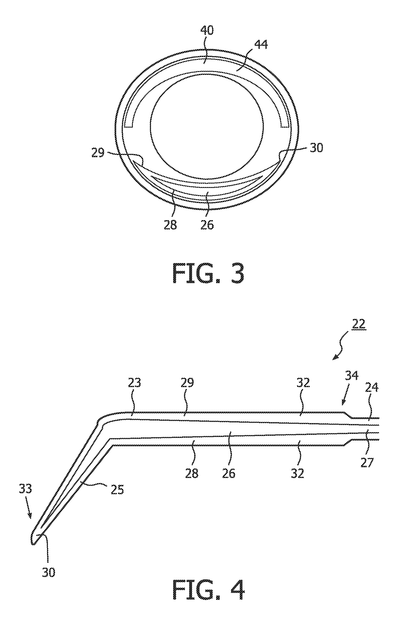
[0065]The progressive deformation of each resiliently deformable membrane wall 28,29 due to the
varying thickness of each wall 28,29 as the pressure in the pressure chamber increases causes the primary insert 22 to impart a peristaltic action on a user's teat which promotes the expression of milk from a user's teat and is more analogous to an infant or baby compared with a conventional breast pump action. Furthermore, an
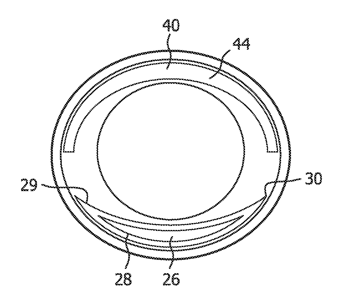
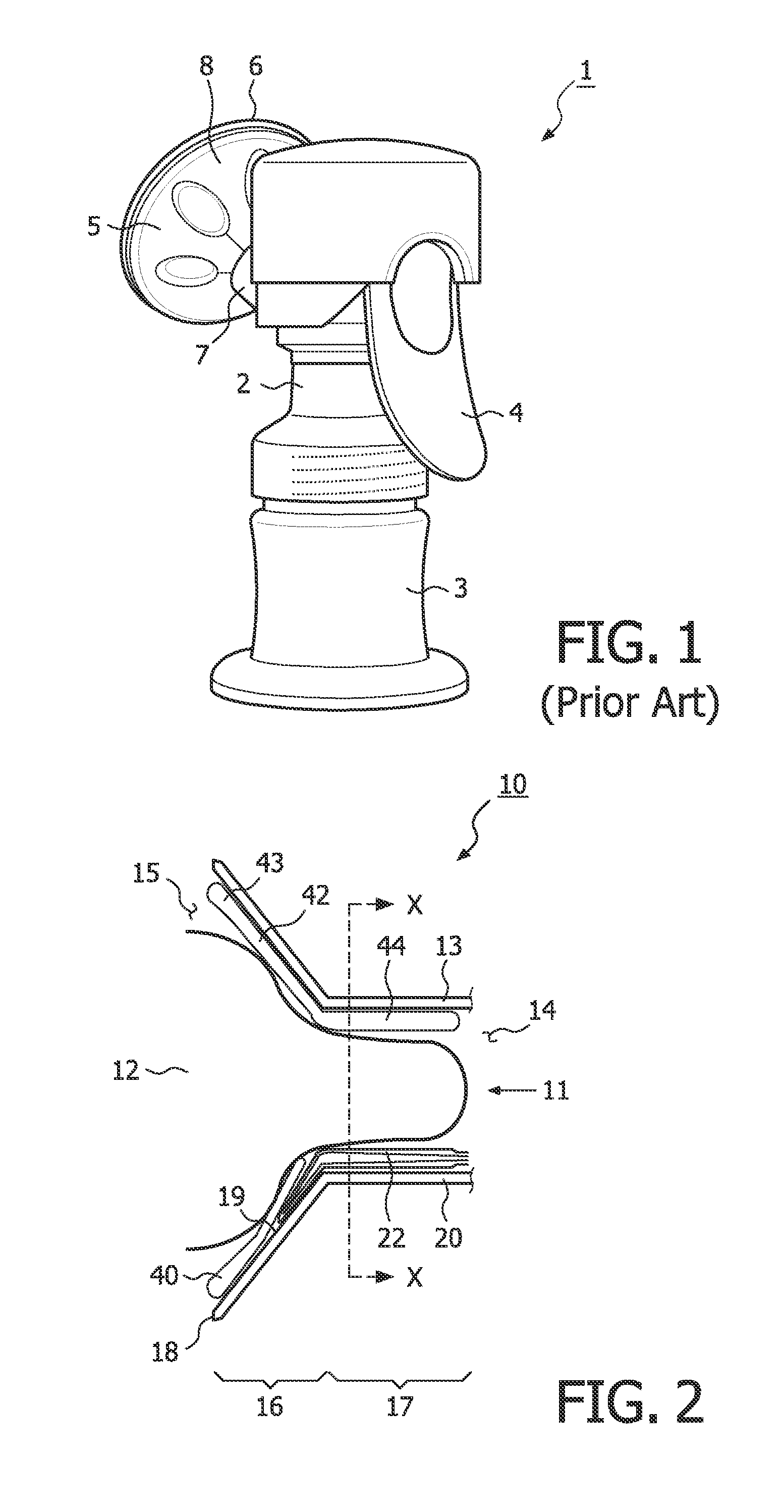
advantage of the present invention is that the primary insert 22 is anatomically similar and has a similar shape and movement as a baby's tongue, and the inner part 44 of the secondary insert 40 is analogous to a baby's palate. Therefore, the natural feel of the breast pump is enhanced. Milk is expressed from the user's breast and is expelled from the funnel 10 through the passageway defined by the outer shell 13 of the funnel 10 into the main body of the breast pump and into the milk receiving vessel.
[0066]As the insert is a bladder with a lower and upper membrane wall 28,29, the insert does not need to be fixedly mounted to the funnel at its outer end to fixedly locate the insert and / or to form a pressure chamber between insert and the outer shell of the funnel in which a
positive pressure can be generated to inflate the bladder. An
advantage of the pressure chamber 26 being formed by the bladder 23 is that it prevents the insert from being mounted to the funnel 10 in an incorrect manner and so causing leakage and loss of function. Furthermore, in a conventional breast pump the deformation of the insert is hampered by attachment of the insert to an outer rim of the funnel. However, in the present arrangement, the insert is not constrained thereby. Additionally, this also allows
predictability of deformation as material folds are not required to allow deformation at the front end of the insert.
[0067]As the resiliently deformable lower and upper membrane walls 28,29 are urged to distend outwardly, the front end 33 of the bladder 23 is urged to distend inwardly towards the inner end 14 of the funnel 10. Therefore, the front end 33 of the bladder 23 and corresponding portion of the upper membrane wall 29 is urged to slide relative to the user's breast disposed in the teat receiving space 11. However, the user's breast is located against the secondary insert 40, which extends over the front end 33 of the bladder 23 and so said front end 33 does not contact the user's breast and friction discomfort is prevented. Furthermore, as the bladder 23 is not fixedly mounted to the outer shell 13 of the funnel, the bladder 23 is not constrained and so is free to inflate without being restrained at the front end 33 of the bladder.
[0068]An
advantage of the front end 33 of the bladder 23 not be constrained is that it aids the progressive deformation of the resiliently deformable membrane walls 28,29 by not restricting said deformation at the front end 33 of the bladder 23 and so said front end 33 can inflate prior to the deformation of the rest of the resiliently deformable membrane walls 28,29 to impart an improved peristaltic action on a user's teat which promotes the expression of milk from a user's teat and is more analogous to that of an infant or baby.
[0069]To cause the resiliently deformable wall 26 to distend inwardly into its original position away from a user's teat, the pressure in the teat receiving space 11 is reduced to reduce the pressure differential. Therefore, the resiliently deformable membrane 23 is urged to distend inwardly into its original position, away from the teat, due to the stiffness and resilient nature of the bladder. As the pressure differential is reduced, the thicker portion of each resiliently deformable membrane wall 28,29 returns to its original shape and position, prior to the thinner portion of each resiliently deformable membrane wall 28,29 returning to its original shape and position.
[0070]By cyclically generating a
positive pressure difference between the pressure chamber 26 and the teat receiving space 11, a repeated peristaltic action is imparted on a user's teat disposed in the teat receiving space 11.

