Power distribution apparatus

a technology of power distribution apparatus and power distribution system, which is applied in the direction of non-electric variable control, process and machine control, instruments, etc., can solve the problems that the produced power distribution system cannot be easily used elsewhere, and the total amount of electrical power required for the operation of the device is considerable, so as to prevent power related damage and good up time

Active Publication Date: 2012-04-05
KONINKLIJKE PHILIPS ELECTRONICS NV
View PDF26 Cites 10 Cited by
  • Summary
  • Abstract
  • Description
  • Claims
  • Application Information

AI Technical Summary

Benefits of technology

[0012]In other words, the power distribution apparatus, according to one aspect of the present invention, allows harnessing the information that resides in the supplied electrical power signal itself in order to effect by suitably switching on / off the soft fuses the provision of high quality power signals and to further allow saving energy.
[0013]The monitoring capabilities also allow detecting non normal behavior in the system that would normally lead with high likelihood to the tripping of the conventional circuit breakers. A plurality of soft fuse switches provide a second layer on top of the existing circuit breaker switches in order to prevent conditions in the system that may lead to the conventional circuit breakers to trip. By switching off the power taps at a point of time before the conventional circuit breaker would trip, an otherwise necessary calling in of a service technician may therefore be avoided and procedure or mission critical equipment can remain in operation. According to another aspect of the present invention, the control module is arranged according to a distributed architecture. The control module in this case is arranged as a master control module and a as a number of slave control modules. The one or more slave control modules are arranged to receive configuration commands from the master control. The commands so received are suitable to effect re-programming any one of the slave modules or to re-program any one of the fuses associated with any one of the one or more slave controllers. The slave and / or the master control modules and / or the fuses are programmable or re-programmable during operation of the power distribution apparatus.
[0015]By having a monitoring module monitor the wave signals of the supplied amperage and voltages at the taps, idle states, non normal behavior, etc. of the connected medical devices at the power taps can be detected. In response to such a detection, control commands are issued from the respective slave or master controller and the respective power tap is switched on or off so as to control the distribution of the available electrical power in a manner that is economical and ensures good up-time characteristics of the connected devices.
[0028]stability and availability (“good up time”) of the one or more medical devices connected.
[0029]Therefore, according to the invention, “controlling the distribution of the electrical power” entails supplying power to the connected devices in manner to prevent power related damage and the then inevitable tripping of the hard fuse in the first place.
[0030]The operation of switching on / off the taps by using the operation of switching off the soft fuses to “control the distribution of the electrical power” is therefore upstream in relation to the operation of switching off the hard fuse (circuit breakers), the hard fuses being installed to ward off imminent damage to the connected loads (medical devices). However, and very much unlike the soft fuses, the hard fuses (“circuit breaker”), once tripped, require manual intervention by a service technician to be switched back on again. In contrast, the soft fuse can be switched off and on by the control module. The soft fuse therefore does not require manual intervention, neither for its being switched on or off. The soft fuse are not installed to primarily ward off imminent damage to the connected medical devices but to ensure long term smooth operation of the connected medical devices.

Problems solved by technology

Further, in large medical facilities where a large number of those medical devices are run at the same time, the total amount of electrical power required for operation of the devices is considerable.
The so produced power distribution systems cannot therefore be used easily elsewhere.

Method used


Image

  • Power distribution apparatus
  • Power distribution apparatus
  • Power distribution apparatus

Examples


Embodiment Construction

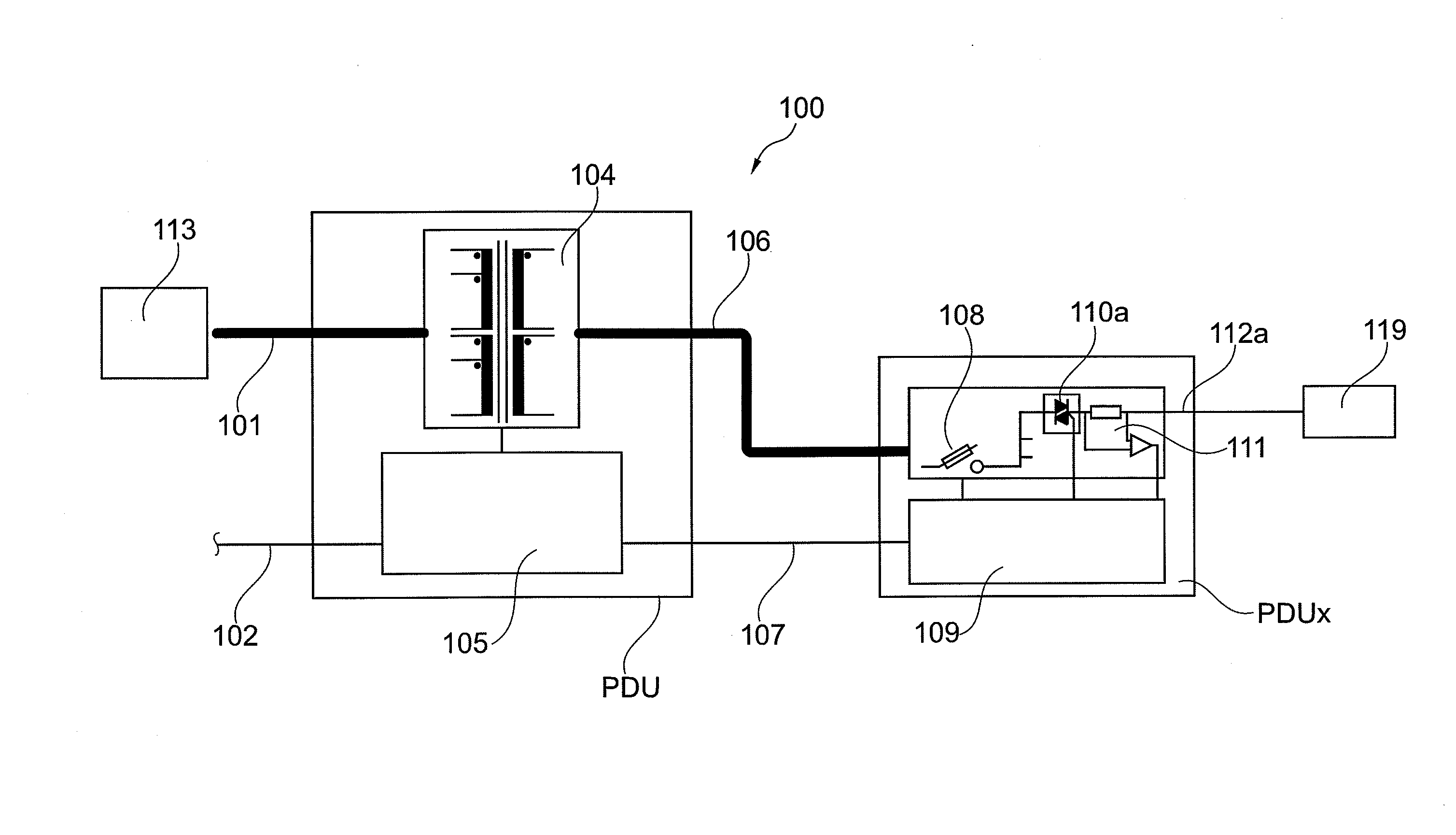
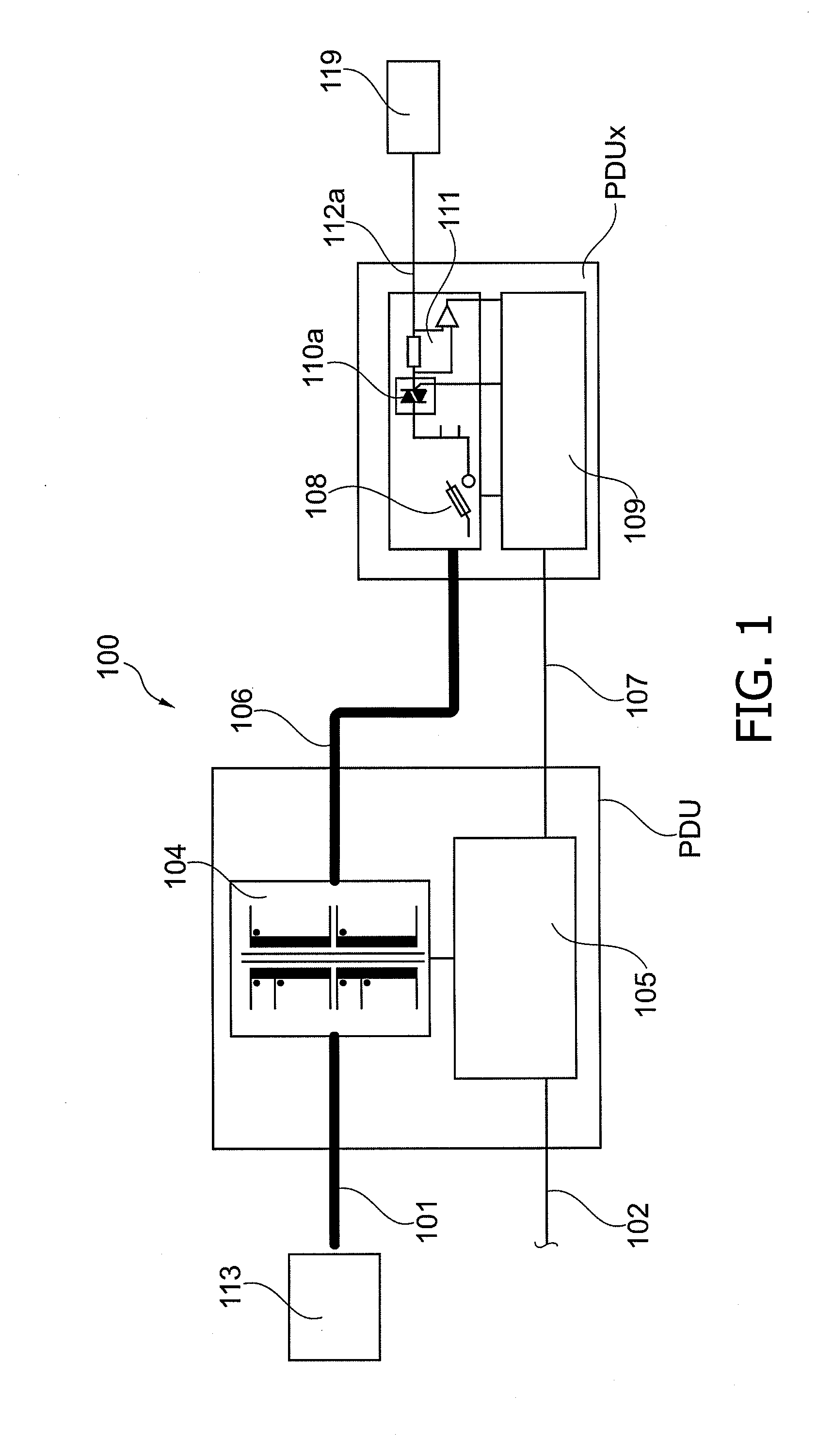
[0041]Reference is now made to FIG. 1 showing a power distribution apparatus 100. The power distribution apparatus 100 may be used in large medical facilities, such as large hospitals or medical centers, having a number of examination rooms. In the examination rooms, medical devices such as medical imaging equipment modality, for example, MRI systems or cardiovascular X-ray systems are placed. The medical devices represent loads 119 that are connectible to a power station 113 providing electrical power. Such connection or ‘hook up’ of the medical devices 119 to the local power station 113 can be achieved efficiently and safely by way of the power distribution apparatus 100. In the following, the terms load(s) and medical device(s) will be used interchangeably and both will be referenced using the same reference numeral ‘119.’ Further examples of the loads 119 in a medical context may include large X-ray system drawing vast currents but also at the other end of the power spectrum sma...


PUM


Abstract

The invention relates to an electrical power distribution apparatus (100) connectible to one or more loads (119). The electrical power distribution apparatus (100) comprises inter alia one or more taps (112) for supplying the loads (119) with electrical power. On top of circuit breakers (108) to switch off the power supply in order to protect the loads against damage, there is also arranged a second layer of soft fuse switches (110) which are arranged to switch on or off the power supply at the taps (112) to control distribution of the power. The soft fuses (110) operate in dependence on and in response to commands issued from a controller (105) which in turn operates and issues those commands in response to and independence on the voltages and amperages monitored at those taps (112) by way of a monitoring module (111). Switching on / off occurs at amperage and voltages lower than the critical threshold values to which the circuit breakers (108) respond to.

Description

FIELD OF THE INVENTION[0001]The invention relates to an electrical power distribution apparatus connectible to one or more loads. The invention further relates to a method of electrical power distribution to one or more loads.BACKGROUND OF THE INVENTION[0002]Modern medical facilities have come to rely these days more and more on dedicated, highly complex medical devices. Such medical devices include imaging equipment such as magnetic resonance imaging (MR) or cardiovascular X-ray systems.[0003]Medical practitioners rely on the imaging material produced by those medical devices. Ensuring smooth operation so that the system can deliver those imaging materials at the required quality level is an objective. When in operation, the medical devices draw electrical power.[0004]Local power stations through their respective power grids supply electrical power. The electrical power supplied is location specific. The power is supplied in certain voltages and amperages at a certain frequency. Th...

Claims


Application Information

Patent Timeline
Patent Type & Authority Applications(United States)
IPC IPC(8): G06F1/28
CPCH02J3/14Y04S20/222Y02B70/3225Y02P80/10H02J2310/60H02J3/144H02J2310/66
Inventor VAN VLIET, JOHANNES ANTONIUSKLEIHORST, ROBERT PAULWAGNER, BERNHARDVAN HELVOORT, MARINUS JOHANNES ADRIANUS MARIALEYMANN, PETER-CHRISTIAN ERICH HEINRICH HAN-JOACHOSTENDORF, ARNO
Owner KONINKLIJKE PHILIPS ELECTRONICS NV
Why Eureka
Try Eureka