Vehicle loading and unloading detection

a technology for loading and unloading and vehicles, applied in the direction of instruments, transportation and packaging, weighing devices, etc., can solve the problems of difficult, if not impossible, to reliably detect the more difficult parts of the mining cycle, and achieve the effect of reliable and accurate determination

Active Publication Date: 2012-04-05
LEICA GEOSYST MINING
View PDF11 Cites 13 Cited by
  • Summary
  • Abstract
  • Description
  • Claims
  • Application Information

AI Technical Summary

Benefits of technology

[0022]Accordingly, some of the advantages of the present disclosure are to provide a more reliable and accurate determination of whether a vehicle is beginning a loading or unloading process, to start a timer so that the amount of time spent performing the loading or unloading may be recorded, and to determine and record a condition of a traveled road. Still further objects and advantages will become apparent from the detailed description and accompanying drawings.

Problems solved by technology

Moreover, capital equipment costs in large mining operations can be quite high.
In current mining operations, one of the more difficult portions of the mining cycle to reliably detect is the start of a loading or unloading process.
Without knowledge of the time in which the loading or unloading process actually started it is very difficult, if not impossible, to accurately determine how long the process takes to complete, or to monitor and evaluate drivers and loaders, determine when a driver is becoming fatigued or slowing down on the job, so that the driver can be relieved or replaced, etc.
If the operator forgets to push the button, or pushes the button too early or too late, any measurement of when the loading process began and how long it took to complete will be inaccurate and unreliable.
One problem with such a method is that often multiple trucks will be present at a loading site at the same time.
GPS alone cannot provide the data necessary to determine when a particular truck begins the loading process.
Moreover, many trucks may sometimes stop near a loading site at shift change, thus frustrating any attempt to determine when a loading process for a particular truck began.

Method used


Image

  • Vehicle loading and unloading detection
  • Vehicle loading and unloading detection

Examples


Embodiment Construction

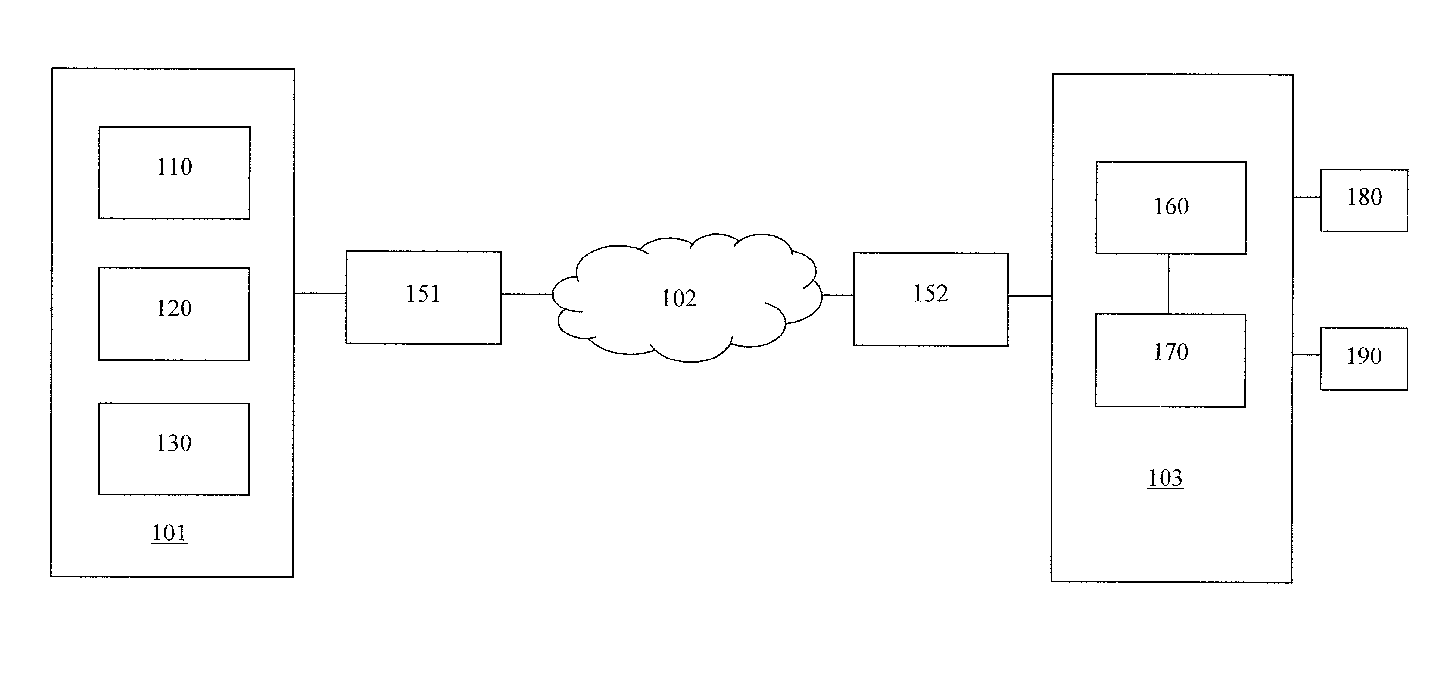
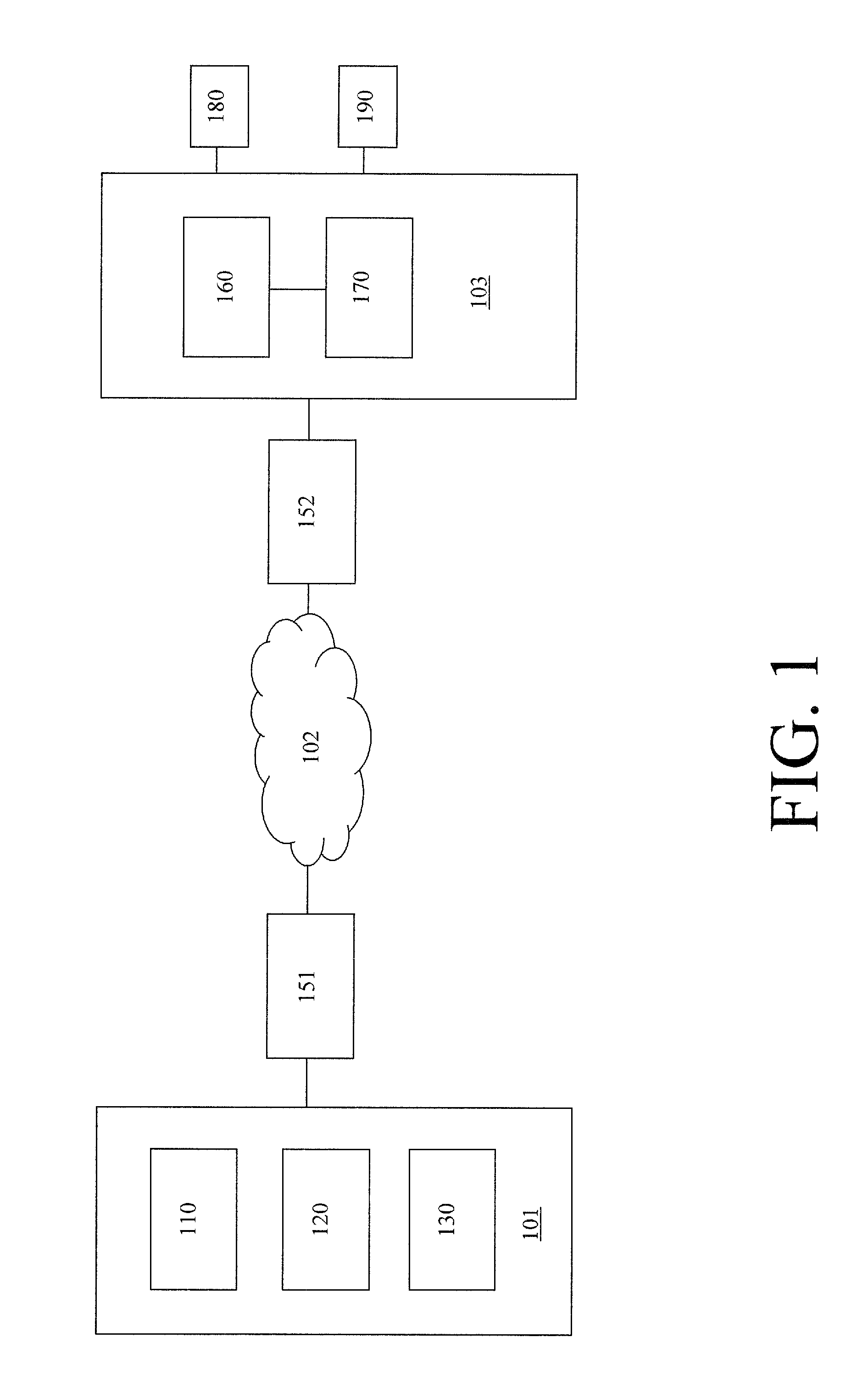
[0026]In the following description, reference is made to the accompanying drawings, which form a part hereof, and in which is shown, by way of illustration, various embodiments of the present disclosure. It is understood that other embodiments may be utilized and changes may be made without departing from the scope of the present disclosure.

[0027]Many embodiments of the invention may take the form of computer-executable instructions, including algorithms executed by a programmable computer. The invention also can be practiced with other computer system configurations as well. Certain aspects of the invention can be embodied in a special-purpose computer or data processor that is specifically programmed, configured or constructed to perform one or more of the computer-executable algorithms described below. Accordingly, the term “computer” as generally used herein refers to any data processor and includes Internet appliances, hand-held devices (including palm-top computers, wearable c...


PUM


Abstract

A system for determining vehicle loading and unloading comprises an acceleration detector provided on a vehicle, a location detector for detecting the location of the vehicle and a processor that receives information detected by the acceleration detector and location detector and determines whether the detected acceleration is due to vehicle loading, unloading or travel, based on the received information. A timer may be started, when vehicle loading or unloading is determined, such that the amount of time spent loading or unloading the vehicle may be obtained. Also, a condition of a traveled surface may be determined based on information received from the acceleration detector and location detector.

Description

FIELD OF THE INVENTION[0001]The present invention relates to a system and method for determining vehicle loading and unloading. The invention has particular utility in connection with mining operations where a measurement of the amount of time spent performing certain processes, such as loading and unloading a vehicle, is an important piece of information that may be used to increase productivity and efficiency of the mining operation. The invention will be described in connection with such utility, although other utilities are contemplated.BACKGROUND OF THE INVENTION[0002]Many current operations rely upon loading a material or product into a vehicle or other equipment. Automation of many of the processes in the operation is a commonly-sought objective to increase productivity and efficiency. For example, many mining operations utilize vehicles to load, haul and unload materials. Increasing the productivity and efficiency of the processes within a mining operation is particularly de...

Claims


Application Information

Patent Timeline
Patent Type & Authority Applications(United States)
IPC IPC(8): G06F15/00G01P15/00
CPCB65G67/00G01G19/08G07C5/008G07C5/0816
Inventor VESTERDAL, STEVEN H.OLSON, JONATHAN P.
Owner LEICA GEOSYST MINING
Why Eureka
Try Eureka