Position determining system

Inactive Publication Date: 2012-04-12
KONINKLIJKE PHILIPS ELECTRONICS NV
View PDF5 Cites 13 Cited by
  • Summary
  • Abstract
  • Description
  • Claims
  • Application Information

AI Technical Summary

Benefits of technology

[0004]It is an object of the present invention to provide a position determining system, a position determining method and a computer program for determining a position of an object, wherein the quality of determining the position can be improved. It is a further object of the present invention to provide a corresponding imaging system, imaging method and computer program for imaging the object.

Problems solved by technology

This system has the drawback that the radiation sent by a transmitter can be partially or completely blocked, for example, by metal objects.
In this case the system cannot work properly anymore and the accuracy of the determined position is decreased or a determination of the position is not possible at all, i.e. the quality of determining the position is reduced.

Method used


Image

  • Position determining system
  • Position determining system
  • Position determining system

Examples


Embodiment Construction

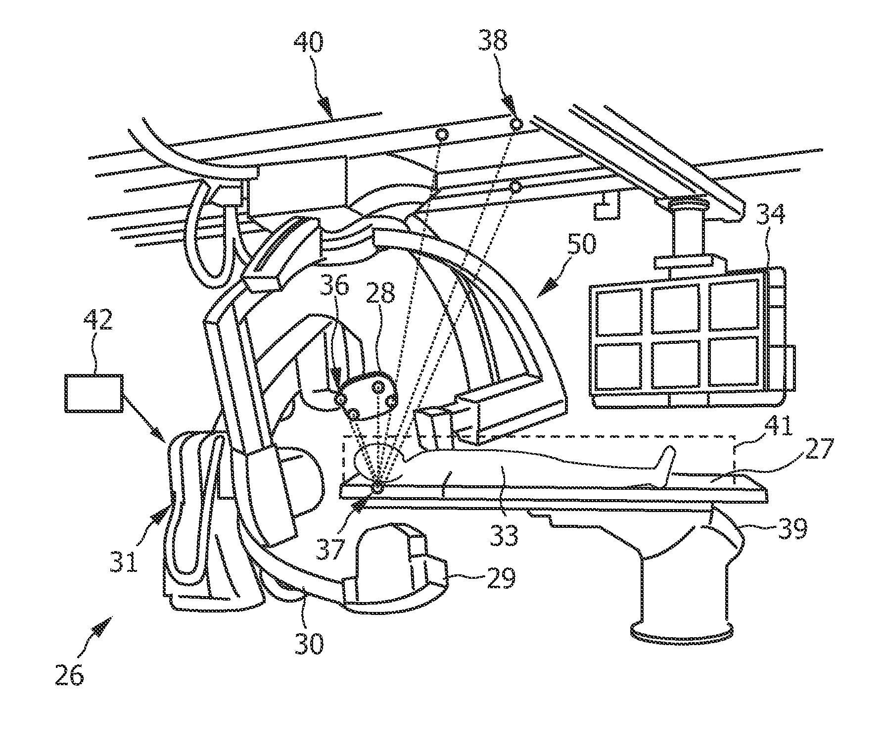
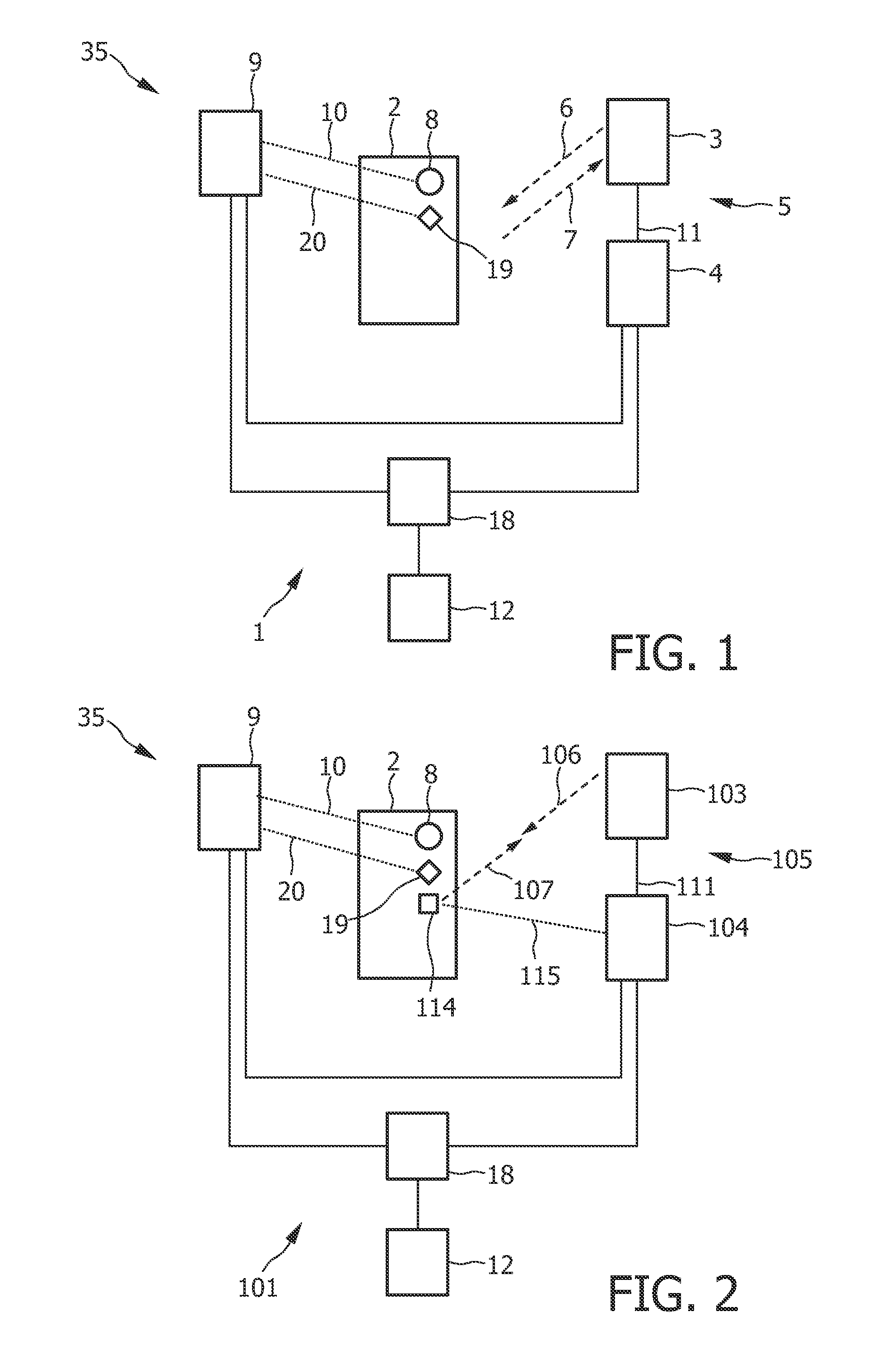
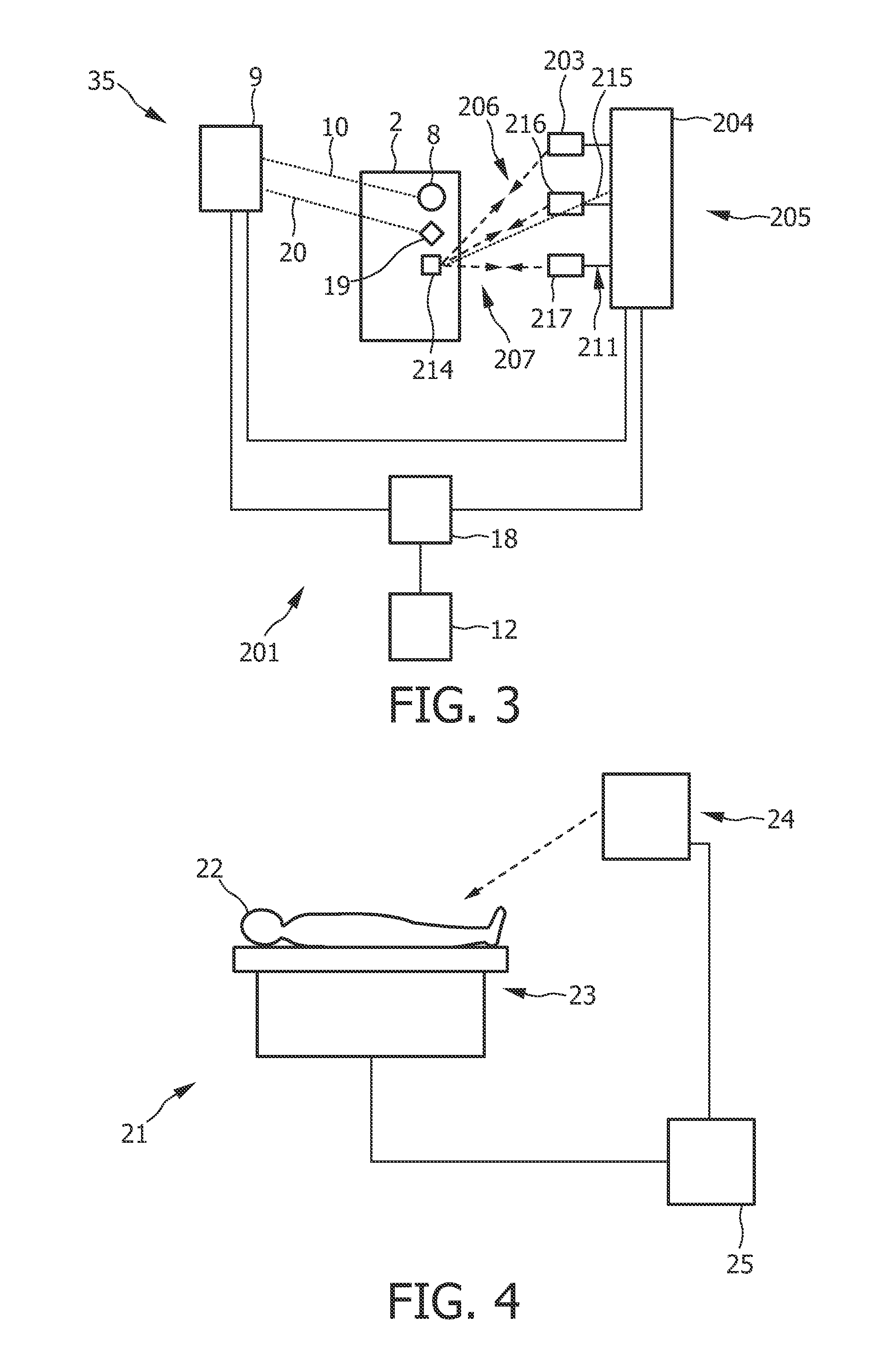
[0068]FIG. 1 shows schematically and exemplarily a position determining system 1 for determining a position of an object 2. The position determining system 1 comprises a first position detection unit 5 and a second position detection unit 35. The first position detection unit 5 comprises a sending and receiving unit 3 for sending radiation 6 to the object 2 and for receiving radiation 7 from the object 2. The first position detection unit 5 further comprises a first position determining unit 4 for determining a first position of the object based on the received radiation 7. The second position detection unit 35 comprises an accelerometer 8, which is attached to the object 2, for determining an acceleration of the object 2. The second position detection unit 35 further comprises a second position determining unit 9 for determining a second position of the object 2 based on the determined acceleration and the determined first position. The sending and receiving unit 3 sends radiation ...


PUM


Abstract

The invention relates to position determining system (201) for determining a position of an object (2). A first position detection unit (205) detects a first position of the object (2) based on radiation transferred between the object (2) and transfer positions being known relative to a reference position by a sending and receiving unit (203, 214, 216, 217). A second position detection unit (35) detects a second position based on an acceleration of the object (2) and the determined first position, wherein an output unit (12) outputs at least one of the first position and the second position. If the transfer of radiation is interrupted, the second position can be output by the output unit. Moreover, the first position can be used as an initial value for determining the second position or to update the second position. This improves the quality of determining the position of the object.

Description

FIELD OF THE INVENTION[0001]The invention relates to a position determining system, a position determining method and a computer program for determining a position of an object. The invention relates further to an imaging system, an imaging method and a computer program for imaging an object.BACKGROUND OF THE INVENTION[0002]U.S. 2008 / 0162046 A1 discloses a system for tracking an arrangement of at least one mobile apparatus in relation to an imaging device, wherein the system includes at least one position monitoring sensor in communication with a controller. The position monitoring sensor is operable to generate a signal indicative of a position of the at least one mobile apparatus relative to a reference point. The controller is operable to calculate a position of the at least one mobile apparatus relative to the imaging device. The at least one position monitoring sensor comprises preferentially transmitters and receivers for transmitting and receiving electromagnetic radiation, w...

Claims


Application Information

Patent Timeline
IPC IPC(8): G01N23/00G01S15/06G01N21/00
CPCG01S5/18G01S2013/468G01S2015/465G01S15/876
Inventor MARCELIS, BOUTVAN HEESCH, CHRISTIANUS MARTINUSKLEE, MAREIKEBABIC, DRAZENKO
Owner KONINKLIJKE PHILIPS ELECTRONICS NV
Why Eureka
Try Eureka