
Multi-source low dose x-ray ct imaging aparatus

a computed tomography and x-ray technology, applied in tomography, applications, instruments, etc., can solve the problems of blurring and degradation of image quality, difficult to image other tissues and organs, blood vessels,

Inactive Publication Date: 2012-04-12
FMI TECH
View PDF36 Cites 6 Cited by
  • Summary
  • Abstract
  • Description
  • Claims
  • Application Information

AI Technical Summary

Problems solved by technology

Other tissues and organs, such as blood vessels, are more difficult to image due to their similarity in attenuation properties relative to the surrounding tissue.
Movements of the portion of the body being imaged can cause blurring and degradation of image quality.
Thus, it is particularly challenging to image the heart, which moves significantly during contraction, i.e. systole, and also due to the subject's breathing.
It is well known in the art that exposure to ionizing radiation, e.g. x-rays, increases a patient's risk of developing certain forms of radiation-induced cancers.
Furthermore, radiation exposure carries an enhanced risk for patients with certain health issues such as patients with pancreatic cancer or patients with an enhanced risk of developing cancer, recent trauma, cirrhosis of the liver, or patients with conditions that require multiple CT scans.

Method used


Image

  • Multi-source low dose x-ray ct imaging aparatus
  • Multi-source low dose x-ray ct imaging aparatus
  • Multi-source low dose x-ray ct imaging aparatus

Examples


embodiment 100

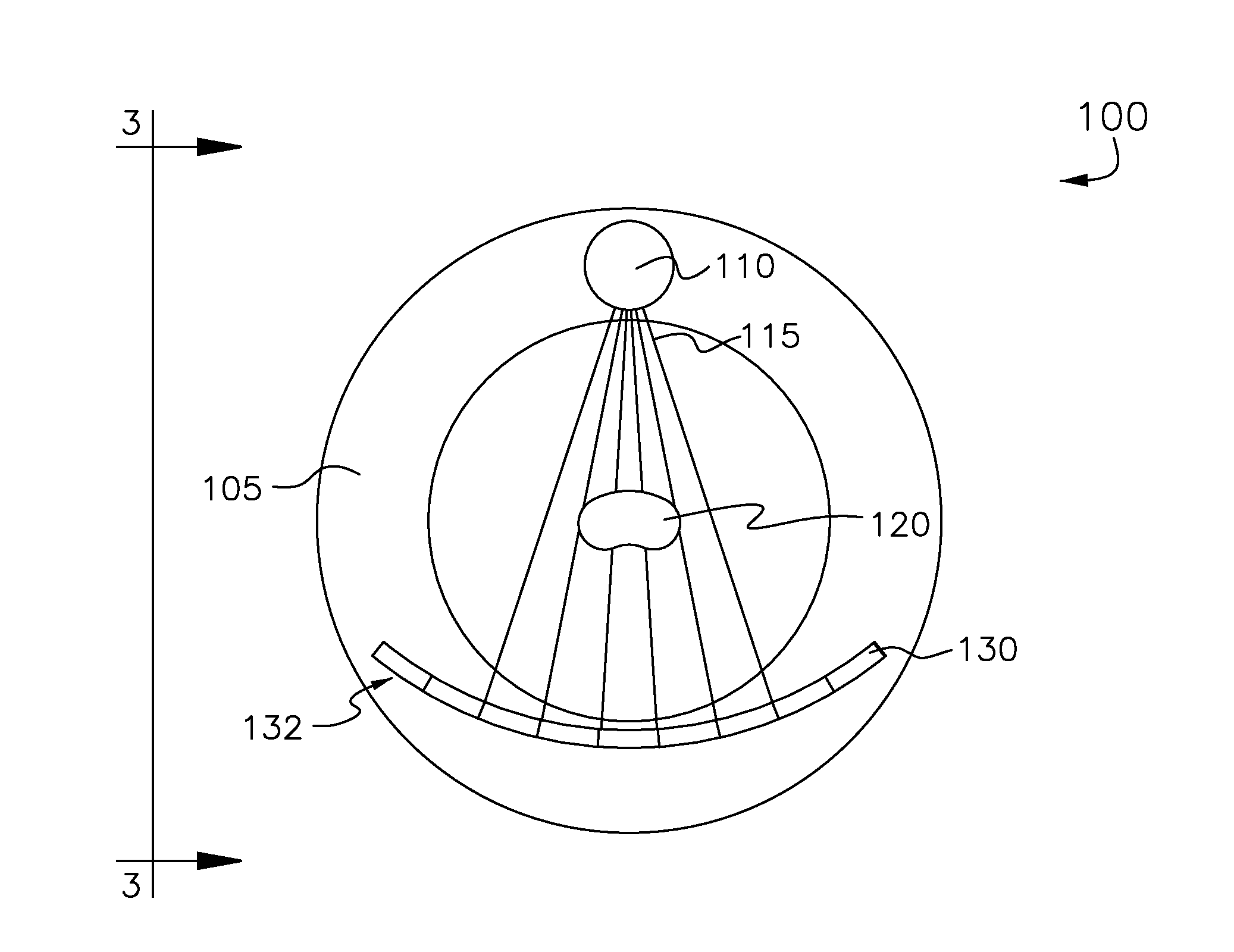
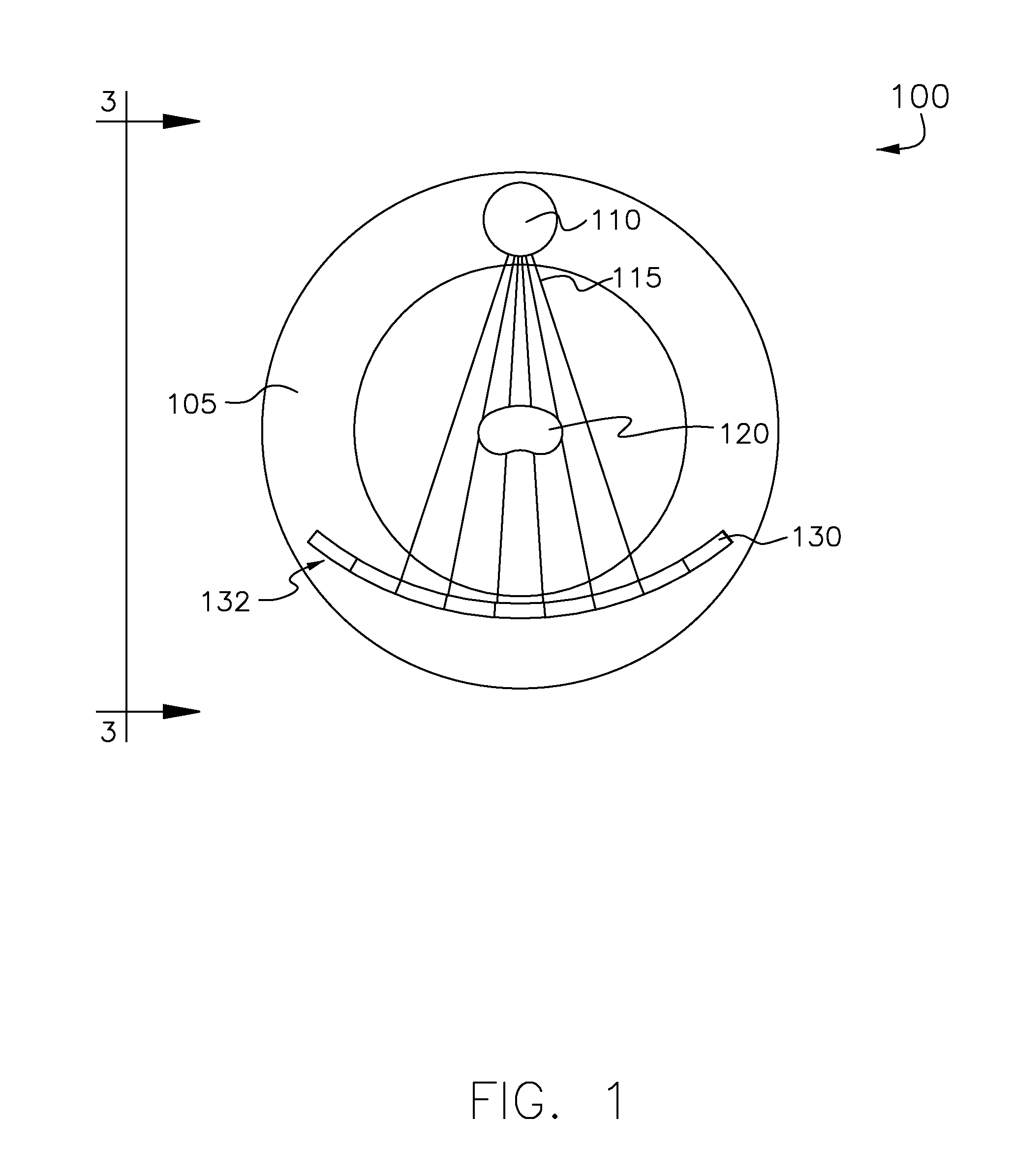
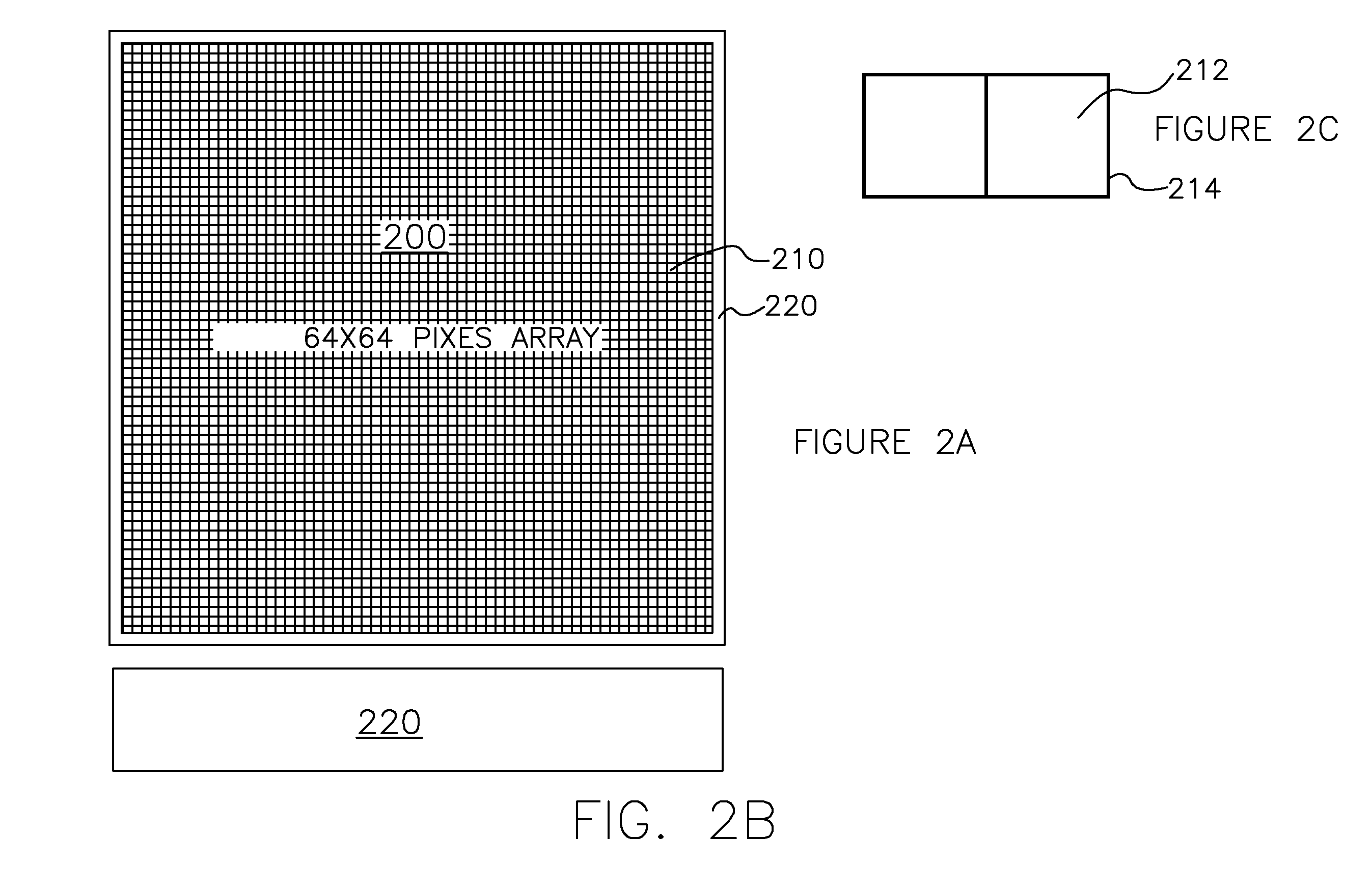
[0039]Turning to FIG. 1, a front view of an embodiment 100 is shown comprising a CT gantry 105 with a dual x-ray source 110 mounted in an upper position. According to this view, the x-ray source 110 emanates x-ray fan beams 115. The fan beams 115 are spaced apart along the z-axis, i.e. in the plane of the page, and therefore are not distinguishable from one another in this view. With continuing reference to FIG. 1, a cross sectional view of a patient 120 is shown attenuating the beams 115, which are then detected by a plurality of x-ray scintillation detectors 130 arranged in an arc 132. In some embodiments, the detectors 130 can comprise, without limitation, a 64×64 pixelated array of LYSO crystals as shown in FIG. 3.

[0040]FIG. 2A-C shows an x-ray scintillation detector 200 consistent with at least some embodiments of the invention. The detector 200 comprises a 64×64 array of LYSO scintillation crystals 210 bounded by a perimeter comprising a brass housing 220. According to FIG. 2C...

embodiment 300

[0041]FIG. 3 shows an embodiment 300 comprising a pair of fixed anode x-ray tubes 310a, 310b. The anodes of tubes 310a and 310b are spaced apart by a distance dz. The tubes 310a, 31b produce fan beams 330a, 330b, which form an overlapping region 340 and impinge on a common overlapping area 342 of a detector 350. According to some embodiments, the fan beams can impinge upon the entire surface of the scintillation detector(s); however, in some embodiments the fan beams can impinge upon less than the entire surface, or may even extend somewhat beyond the detector(s) surface.


PUM


Abstract

Some embodiments include a low-dose CT apparatus. Such an apparatus can comprise a plurality of x-ray sources disposed on a gantry and spaced apart along a z-axis. The sources may be configured to produce substantially overlapping fan beams, wherein overlap is substantially complete at a detector surface. Some embodiments also include a controller in electronic communication with the plurality of x-ray sources. The controller may be adapted to switch the plurality of x-ray sources between on and off states such that only one x-ray source is in an on state at any time. Furthermore, the controller circuit may be in electronic communication with at least one x-ray detector and may be adapted to synchronize the x-ray detector with the plurality of x-ray sources such that detected x-rays can be matched to an x-ray source.

Description

I. CROSS-REFERENCE TO RELATED APPLICATIONS[0001]This application claims priority to U.S. Provisional Patent Application No. 61 / 391,621 filed Oct. 9, 2010 and now pending, and which is incorporated by reference in its entirety.II. BACKGROUND OF THE INVENTION[0002]A. Field of Invention[0003]This invention generally relates to low-dose x-ray sources for x-ray computed tomography systems.[0004]B. Description of the Related Art[0005]In general, x-ray computed tomography (CT) is conducted using an x-ray source, such as a rotating anode source, mounted on a gantry with one or more x-ray scintillation detectors disposed in an opposing orientation. The gantry typically includes a central aperture for receiving a patient such that the patient is disposed between the source and detector(s). Thus, an x-ray beam passes from the source through the patient and an attenuated x-ray intensity pattern is measured by the detector. Typically, the gantry rotates the source and detectors about the patient...

Claims


Application Information

Patent Timeline
Patent Type & Authority Applications(United States)
IPC IPC(8): A61B6/03
CPCA61B6/032A61B6/541A61B6/4007
Inventor MCCROSKEY, WILLIAM K.MILLIFF, TIMOTHY W.HEIPP, CHRIST H.
Owner FMI TECH
Learn More