Structural longitudinal composite joint for aircraft structure

a composite joint and longitudinal technology, applied in the field of structural composite parts, can solve the problems of weakening of structural composite parts and labour costs, and achieve the effects of reducing thermal linear expansion, optimal handling, and ensuring stability

Inactive Publication Date: 2012-04-12
SAAB AB
View PDF1 Cites 14 Cited by
  • Summary
  • Abstract
  • Description
  • Claims
  • Application Information

AI Technical Summary

Benefits of technology

[0014]The reinforced composite joint made structural by the nanostructure arranged within the composite joint will thereby provide the structural composite part a strength in x-, y-, z-direction. The reinforced composite joint will have a reduced thermal linear expansion and the viscosity can be controlled by the amount of nanostructure for an optimal handling of the reinforced composite joint under production.
[0039]Thereby is achieved, when using ATL-machine lay-up, a cost effective production of single and double curved structural composite parts. The forming means that a vacuum bag can be used for achieving a pressure on the stack over a forming tool. Trapped air and wrinkles being forced out under vacuum pressure. If a stronger forming force is required for forming the stack over a specific portion of the forming tool, the stack can be arranged in such way that the lay-up of pre-preg tapes will have one or several of their joined nanostructure reinforced composite joints positioned over that specific portion for easier forming due to the viscosity of the nanostructure composite joint. After fulfilled forming the formed pre-preg stack is cured.

Problems solved by technology

This prior art joint is weakening the structural composite part and may also imply a cost of labour if the edges of the laid up pre-impregnated fibre plies overlap each other, wherein the overlapping edge of the pre-impregnated fibre ply must be cut.

Method used


Image

  • Structural longitudinal composite joint for aircraft structure
  • Structural longitudinal composite joint for aircraft structure
  • Structural longitudinal composite joint for aircraft structure

Examples


first embodiment

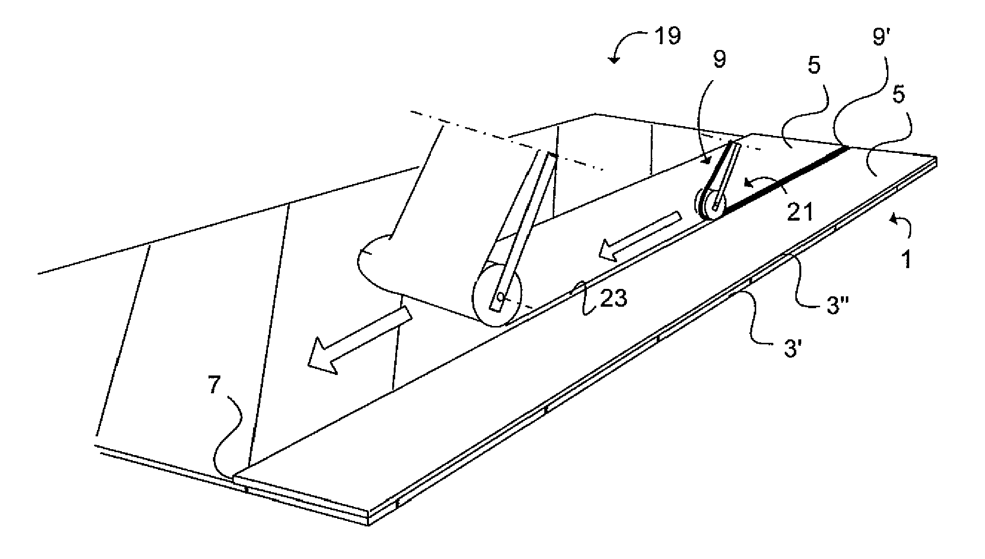
[0062]FIG. 3a illustrates an Automatic Tape Laying (ATL)-machine 19 according to a The function of a common ATL-machine is known in the art. The in FIG. 3a shown machinery is added with a nanostructure composite joint material layer unit 21. A storage reel (not shown) comprising winded nanostructure composite joint 9 material in the form of a nanostructure tape 9′ is fed into the gap 23 between two in a common plane earlier laid adjacent pre-preg tapes 5, which have been laid by the main unit ATL 19. After that the main unit ATL 19 has been driven to a predetermined end of the stack 1, the pre-preg tape 5 is cut by a knife (not shown). The main unit ATL 19 is operated to a position at the beginning end of the stack 1 and applies a further strip of pre-preg tape 5 onto the stack 1. For achieving a fast production, the main unit ATL is set to a high speed modus, wherein the gap 23 between two in advance laid pre-preg tapes in a common plane can be allowed wider than that which has to...

second embodiment

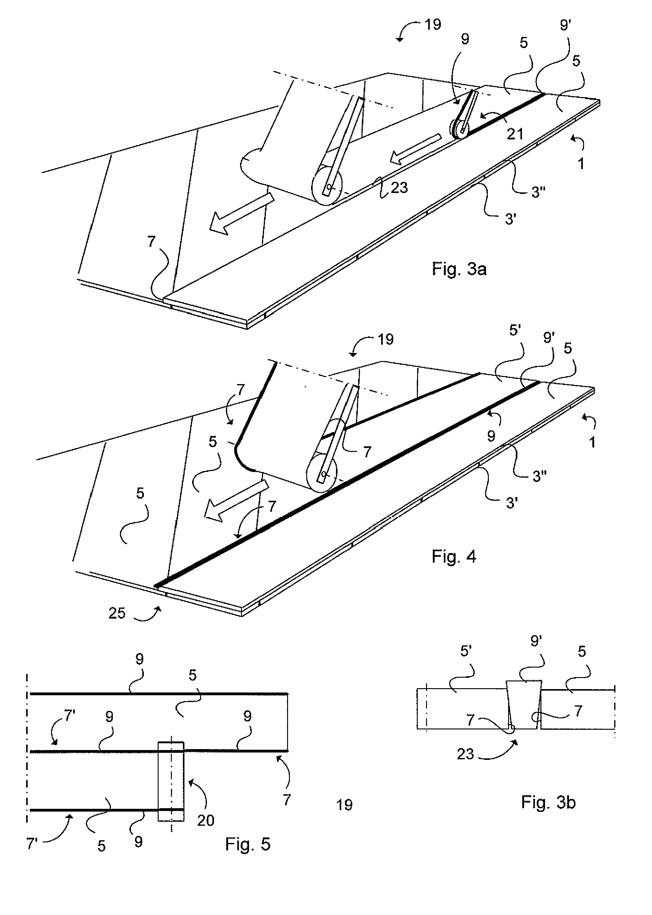
[0066]FIG. 4 illustrates an Automatic Tape Laying machine 19 according to a According to this embodiment the pre-preg tape 5 has been provided with a nanostructure reinforced composite joint 9 material on one prolonged side 25 edge in advance. The nanostructure tape 9′ is thus applied onto the pre-preg tape 5 before the latter is applied onto the stack 1. The other prolonged edge of the pre-preg tape 5 does not have any nanostructure tape. The prepared pre-preg tape 5′ is laid parallel with an earlier laid prepared pre-preg tape 5 and their edges 7 are thus connected via the nanostructure reinforced composite joint 9 of the earlier laid pre-preg tape 5.

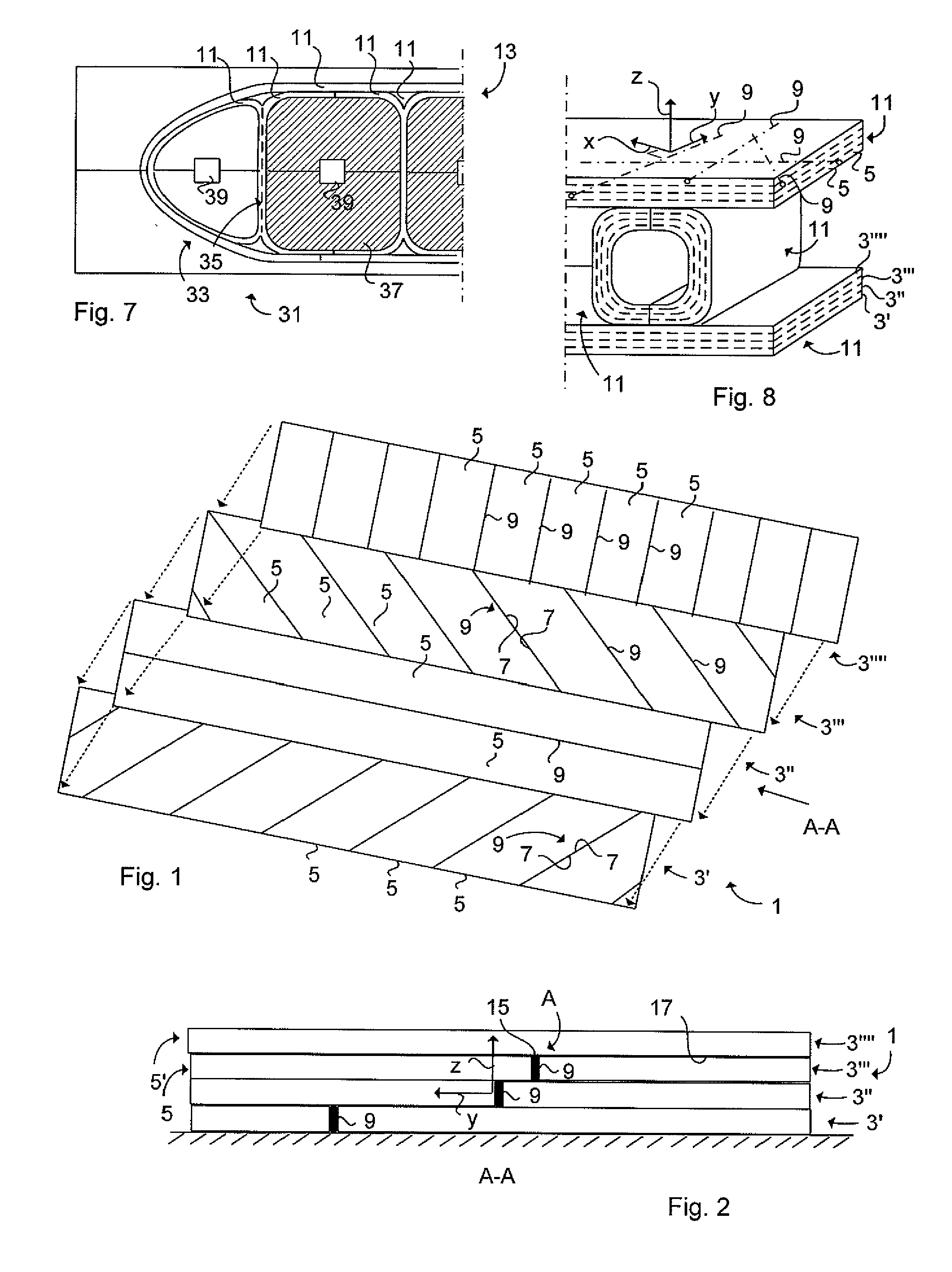
[0067]The method of producing the structural composite part 11 made of pre-preg tapes 5 laid-up almost edge 7 edge 7 and onto each other is described as follows. The edges 7 of two adjacent pre-preg tapes 5 are connected via the longitudinal nanostructure reinforced composite joint 9 extending in the longitudinal direction of the edg...

third embodiment

[0069]FIG. 5 illustrates an Automatic Tape Laying machine 19 wherein the stack 1 is created by means of an ATL main unit 20 feeding a pre-preg tape 5 having nanostructure composite joints 9 one both edges 7′ of the pre-preg tape 5. The respective pre-preg tape's 5 nanostructure composite joints 9 are flowing into each other when the edges 7 and 7′ of the respective pre-preg tape 5 are meeting each other.

[0070]FIG. 6 schematically illustrates the forming tool 27. The stack 1 is positioned over the forming tool and are conformed over the forming tool's forming surface, wherein a U-beam is formed. The U-beam is assembled together with other structural composite parts later on for building an aircraft structure, as shown in FIG. 7.

[0071]FIG. 7 illustrates a curing tool 31 for the assembly of structural composite parts 11 forming an aircraft structure 13. The structural composite parts 11 are bonded to each other via a bonding interlayer material (not shown) to form the aircraft structur...


PUM

PropertyMeasurementUnit
diameteraaaaaaaaaa
diameteraaaaaaaaaa
shapeaaaaaaaaaa

Abstract

A structural composite part made of pre-impregnated fiber plies. The edges of two adjacent fiber plies are connected via a longitudinal composite joint made structural by a nanostructure arranged within the composite joint. A method of producing a structural composite part made of pre-impregnated fiber plies. The edges of two adjacent fiber plies are connected via a longitudinal composite joint made structural by a nanostructure and an aircraft structure comprising such structural composite parts.

Description

TECHNICAL FIELD[0001]The present invention relates to a structural composite part according to the preamble of claim 1. The present invention also relates to a method according to claim 9 for producing the structural composite part.BACKGROUND ART[0002]Structural composite parts for aircrafts may be produced by mechanical forming or hot drape forming of a blank or stack of layers comprising pre-impregnated fibre plies (pre-preg tapes), each layer having fibres with a specific fibre direction. The stack is produced by laying up in a plane parallel with each other almost edge edge pre-fabricated pre-preg tapes. Between the edges often occurs a gap. The gap will be closed by the next layer laid upon the first layer. This means that longitudinal gaps in each pre-preg tape plane often occurs in the stack and which will weaken the finished structural composite part.[0003]For example, a wing (aircraft structure) may comprise assembled upper and lower shells, beams, wing ribs (three-dimensio...

Claims


Application Information

Patent Timeline
Patent Type & Authority Applications(United States)
IPC IPC(8): B32B3/14B32B7/14B32B7/03B82Y30/00
CPCB29C70/30Y10T428/18B29K2031/00B29K2063/00B29K2067/00B29K2071/00B29K2079/085B29K2081/04B29K2101/10B29K2101/12B29K2105/06B29K2105/167B29K2307/00B29K2309/02B29K2309/08B29L2031/3076B29L2031/3085B32B3/02B32B5/26B32B5/28B64C3/20B64C3/26Y02T50/433Y02T50/43B29C66/721B29C70/58Y10T428/16Y10T428/17B29C66/435B29C65/4875B29C65/488B29C65/5014B29C65/5021B29C66/43B29C66/1142B29C65/5057B29C65/00B32B5/02B32B5/22B32B3/14B32B3/18B32B2250/20B32B2260/021B32B2260/046B32B2262/02B32B2262/101B32B2262/105B32B2262/106B32B2307/50B32B2307/558B32B2605/18B32B7/03Y02T50/40B29C70/304
Inventor HALLANDER, PERPETERSSON, MIKAELWEIDMANN, BJORNGRANKALL, TOMMYSTRINDBERG, GOTENORDIN, PONTUSONNEFORS, RUSTAN
Owner SAAB AB
Why Eureka
Try Eureka