Nano-reinforced radius filler for an aircraft structure and a method of producing an aircraft structure comprising such filler

a technology of nano-reinforced radius and aircraft structure, which is applied in the field of composite radius fillers, can solve the problems of affecting the cost effectiveness of the aircraft structure, the viscosity of the resin of the radius filler can be reduced, and the radius filler may be separated from the structural composite part, etc., and achieves cost-effectiveness and viscosity. the effect of the resin of the radius filler

Inactive Publication Date: 2012-03-29
SAAB AB
View PDF23 Cites 19 Cited by
  • Summary
  • Abstract
  • Description
  • Claims
  • Application Information

AI Technical Summary

Benefits of technology

[0033]Suitably, the viscosity of the resin of the radius filler can be controlled by the amount of nanostructure for an optimal handling of the comp...

Problems solved by technology

Such a composite radius filler weakens the finished aircraft structure, especially within the interface area between the composite radius filler and the surface of the structural composite parts.
The composite radius filler according to prior art thus may tear apart and crack within said interface area due to tear and shear strain.
Also, the radius filler m...

Method used


Image

  • Nano-reinforced radius filler for an aircraft structure and a method of producing an aircraft structure comprising such filler
  • Nano-reinforced radius filler for an aircraft structure and a method of producing an aircraft structure comprising such filler

Examples


first embodiment

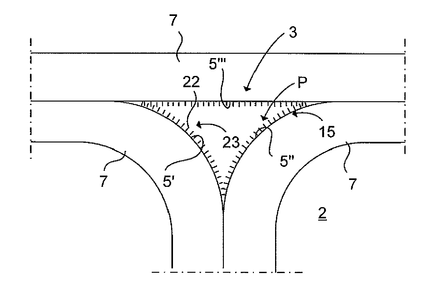
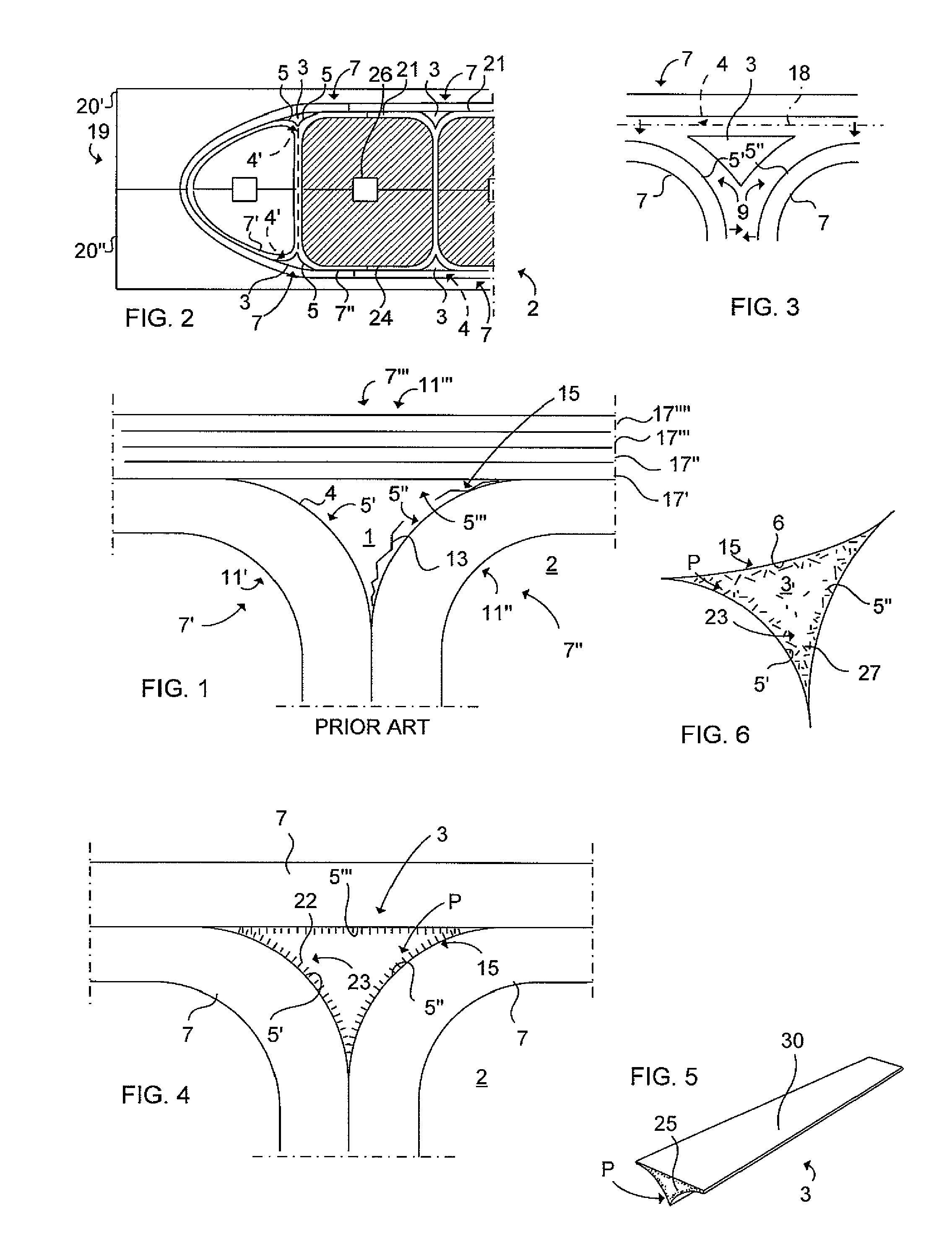
[0049]In FIG. 4 the radius filler 3 is schematically illustrated in a cross section according to the The composite radius filler is thus made structural by the nanostructure 23 arranged within the composite radius filler 3. According to this embodiment the nanostructure primarily is arranged in the periphery P of the composite radius filler for reinforcement of the interface area 15 between the composite radius filler 3 and the structural composite parts 7. The nanostructure 23 is in the form of nanofibers 22 and is oriented perpendicular against the respective structural composite part 7. In this way the aircraft structure 2 can be reinforced effective by means of a cost-effective feature in addition which is of low weight, meaning that the overall weight of the aircraft can be reduced. The nanostructure 23 located in the periphery P of the radius filler 3 hinders that any cracks will appear in the radius filler 3 near the interface area 15 between the radius filler 3 and the stru...

second embodiment

[0052]FIG. 5 illustrates a perspective view of a prolonged radius filler 3 according to a The nanostructure 23 comprises nanotubes 25 having a unidirectional orientation along the prolongation of the radius filler 3. The nanotubes 25 are located in the periphery P of the composite radius filler 3 for reinforcement of the interface area 15 between the composite radius filler 3 and the structural composite parts 7. The prolongation of the nanotubes is thus parallel with the prolongation of the radius filler, i.e. perpendicular to a plane corresponding with the shown triangular cross section of the radius filler 3.

[0053]In FIG. 5 is shown a radius filler 3 being arranged with a protective tape 30 for protecting the radius filler and to simplify the handling of the radius filler 3 in the production line. Also the viscosity can be controlled by the amount of nanostructure for an optimal handling of the composite radius filler under production. The radius filler 3 comprises a resin, whic...

third embodiment

[0054]FIG. 6 schematically illustrates a cross section of a radius filler 3 according to a The nanostructure comprises nanowires 27 being oriented unhomogeneous with a major part positioned in the periphery P of the composite radius filler 3 for reinforcement of the interface area 15 between the composite radius filler 3 and the structural composite parts 7. The nanowires 27 located within the periphery P of the radius filler 3 hinders that any cracks appear in the radius filler 3 near the interface area 15, which is a transition zone between the radius filler 3 and the structural composite part 7, during heavy stressing of the aircraft. The radius filler 3 in FIG. 6 has a triangular cross-section with three convex outer surfaces 5′, 5″, 6.


PUM

PropertyMeasurementUnit
Radiusaaaaaaaaaa
Areaaaaaaaaaaa

Abstract

A composite radius filler for use in an aircraft structure. The aircraft structure includes structural composite parts assembled together to form the aircraft structure. The composite radius filler is arranged between rounded sections of the structural composite parts for filling a gap formed between the structural composite parts. The composite radius filler is made structural by a nanostructure arranged within the composite radius filler for the reinforcement of the interface between the radius filler and the structural composite part. A method for producing an aircraft structure including a nano-reinforced radius filler.

Description

TECHNICAL FIELD[0001]The present invention relates to a composite radius filler according to the preamble of claim 1 and a method of producing an aircraft structure according to claim 10.BACKGROUND ART[0002]When producing an integrated monolithic structure (also called an aircraft structure such as a wing, rudder, flap etc) for an aircraft (such.), structural composite parts (such as semi-cured and pre-formed plastic beams, resin shells etc.) are cured together with a composite radius filler filling a gap between the structural composite parts being connected. The gap is formed by at least two rounded sections of rounded or curved areas of the respective structural composite part facing each other.[0003]The composite radius fillers are thus arranged between the rounded sections of the structural composite parts (such as composite laminates) for filling the gap between structural composite parts' rounded areas. The radius filler is thus applied in the aircraft structure for preventin...

Claims


Application Information

Patent Timeline
IPC IPC(8): B64C9/00C08L63/00C08L35/00C08L31/02C08L79/04C08L61/16C08L61/06C08L79/08C08L81/04C08L79/00C08L67/00B32B37/12B32B37/14B32B3/26C08K3/04B82Y30/00
CPCB29C35/02Y10T428/24479B29C66/721B29C70/14B29C70/46B29K2105/06B29K2105/167B29K2105/243B29K2307/00B29L2031/3076B29L2031/3082B29L2031/3085B64C1/06Y02T50/433B29C66/43441B29C66/7212B29C66/71B29C66/72141B29C66/73754B29C66/73941B29C65/02B29C66/49B29C66/496B29C66/112B29C66/1122B29C66/131Y02T50/40B29D99/0005B29K2307/04B29K2071/00B29K2067/00B29K2063/00B29K2031/00B29K2049/00B29K2061/04B29K2079/08B29K2081/04
Inventor HALLANDER, PERPETERSSON, MIKAELWEIDMANN, BJORNGRANKALL, TOMMYSTRINDBERG, GOTENORDIN, PONTUS
Owner SAAB AB
Why Eureka
Try Eureka