
Diagnosis assisting apparatus, diagnosis assisting program, and diagnosis assisting method

a technology of assisting diagnosis and apparatus, applied in the field of assisting diagnosis apparatus, method, computer program, etc., can solve the problems of requiring time for understanding cardiac motion, and difficulty in understanding the direction of each region of the heart based on the phase change,

Inactive Publication Date: 2012-04-12
FUJIFILM CORP
View PDF3 Cites 28 Cited by
  • Summary
  • Abstract
  • Description
  • Claims
  • Application Information

AI Technical Summary

Benefits of technology

[0015]a display control means for displaying the generated two-dimensional image on a display device and superimposing a mark representing the first index value calculated by the first index value calculation means on the displayed two-dimensional image in a manner that allows the direction of motion of the first index value to be visually recognized.
[0021]displaying the generated two-dimensional image on a display device and superimposing a mark representing the first index value calculated by the first index value calculation means on the displayed two-dimensional image in a manner that allows the direction of motion of the first index value to be visually recognized.
[0027]a display control means for displaying the generated two-dimensional image on a display device and superimposing a mark representing the first index value calculated by the first index value calculation means on the displayed two-dimensional image in a manner that allows the direction of motion of the first index value to be visually recognized.
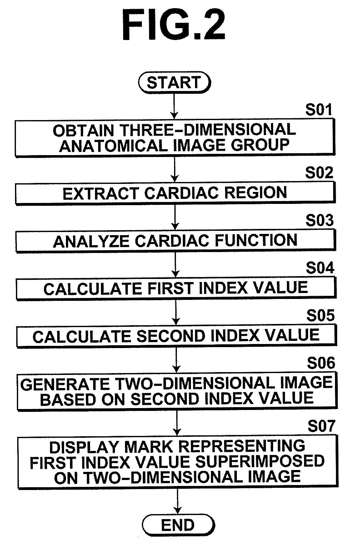
[0040]According to the diagnosis assisting apparatus, method, and program of the present invention, a mark representing a first index value is superimposed on a two-dimensional image of the entire heart in which the second index value of each portion of the heart is disposed in a planar fashion in a manner that allows the direction of motion of the first index value to be visually recognized, so that index values that serve as diagnostic indicators of the entire heart and the direction of motion of each cardiac portion may be displayed simultaneously on the displayed image. This allows the doctor or radiologist to confirm both the index values serving as diagnostic indicators of the entire heart and direction of motion of each cardiac portion on the displayed image, whereby the index values serving as diagnostic indicators of the entire heart and direction of motion of each cardiac portion may be easily understood.
[0041]In the diagnosis assisting apparatus of the present invention, in the case where the image obtaining means is a means that further obtains a three-dimensional functional image in which evaluation values for evaluating function of the heart are disposed three-dimensionally according to the shape of the heart, and the second index value calculation means is a means that calculates the second index value that serves as a diagnostic indicator from the three-dimensional functional image instead of at least either one of the three-dimensional anatomical image at the given phase and the three-dimensional anatomical image group, index values that serve as diagnostic indicators of the entire heart and the direction of motion of each cardiac portion may be displayed simultaneously on the displayed image. This allows the doctor or radiologist to confirm both the index values serving as diagnostic indicators of the entire heart and direction of motion of each cardiac portion on the displayed image, whereby the index values serving as diagnostic indicators of the entire heart and direction of motion of each cardiac portion may be easily understood.
[0047]Further, in the diagnosis assisting apparatus of the present invention, in the case where the two-dimensional image generation means is a means that generates a bull's eye image as the two-dimensional image, index values that serve as diagnostic indicators of the entire heart and the direction of motion of each cardiac portion may be displayed simultaneously in the displayed bull's eye image. This allows the doctor or radiologist to confirm both the index values serving as diagnostic indicators of the entire heart and direction of motion of each cardiac portion in the displayed bull's eye image, whereby the index values serving as diagnostic indicators of the entire heart and direction of motion of each cardiac portion may be easily understood.

Problems solved by technology

The method described in Japanese Unexamined Patent Publication No. 2002-306483, however, poses problems that it is necessary to display and confirm three-dimensional contours of a heart from a plurality of directions in order to obtain motion information of the entire heart, and it is necessary to display and compare a plurality of three-dimensional contours of different phases in order to confirm the trajectory of motion of a specific apex of the heart, thereby requiring time for understanding cardiac motion.
The method described in U.S. Patent Application Publication No. 20090043200 may confirm a region in which cardiac mechanical motion is not less than a predetermined value with respect to each phase, but it is difficult to understand which direction each region constituting the heart moves according to the phase change.

Method used


Image

  • Diagnosis assisting apparatus, diagnosis assisting program, and diagnosis assisting method
  • Diagnosis assisting apparatus, diagnosis assisting program, and diagnosis assisting method
  • Diagnosis assisting apparatus, diagnosis assisting program, and diagnosis assisting method

Examples


Embodiment Construction

[0058]Hereinafter, embodiments of a diagnosis assisting apparatus, diagnosis assisting program, and diagnosis assisting method of the present invention will be described in detail with reference to the accompanying drawings.

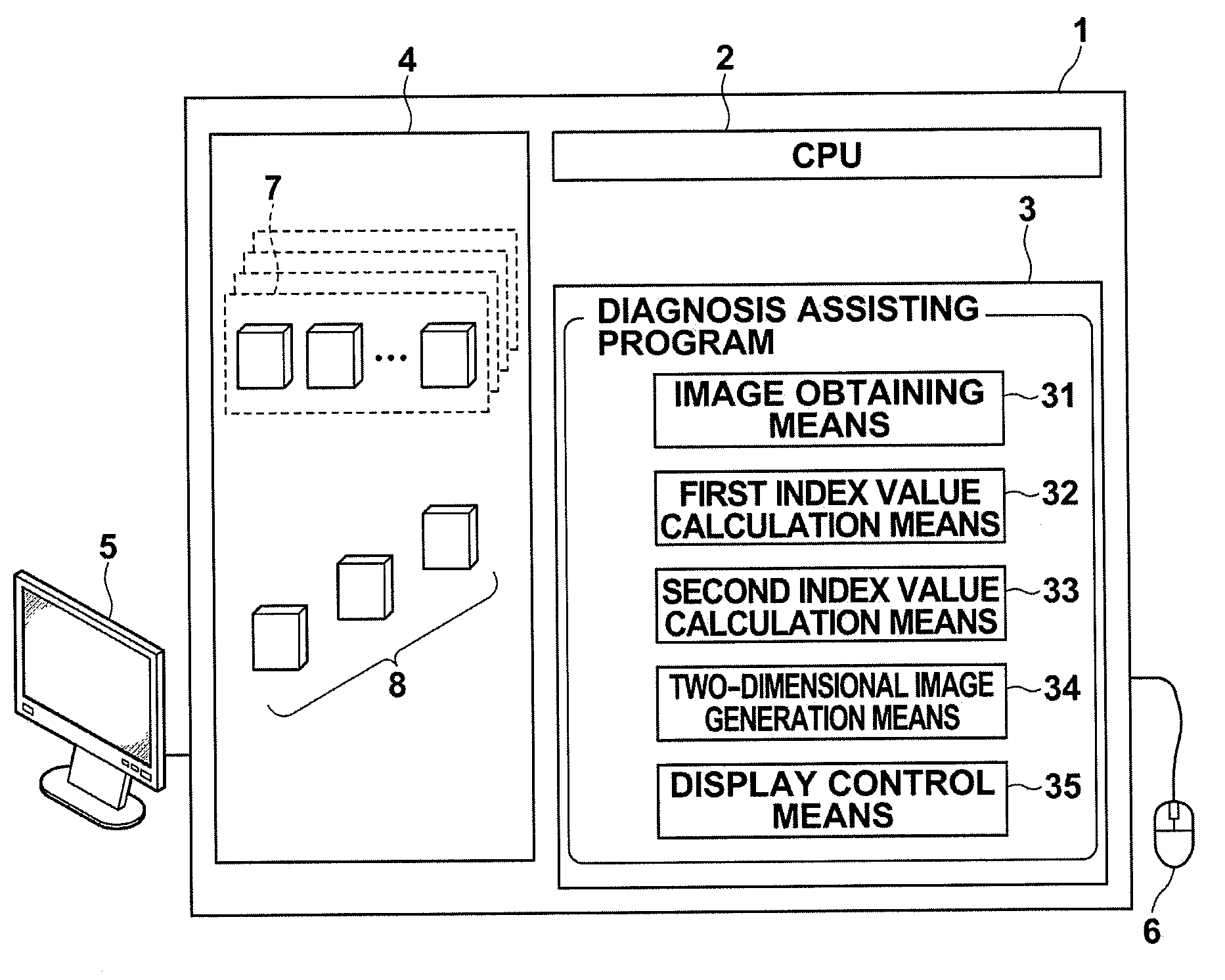
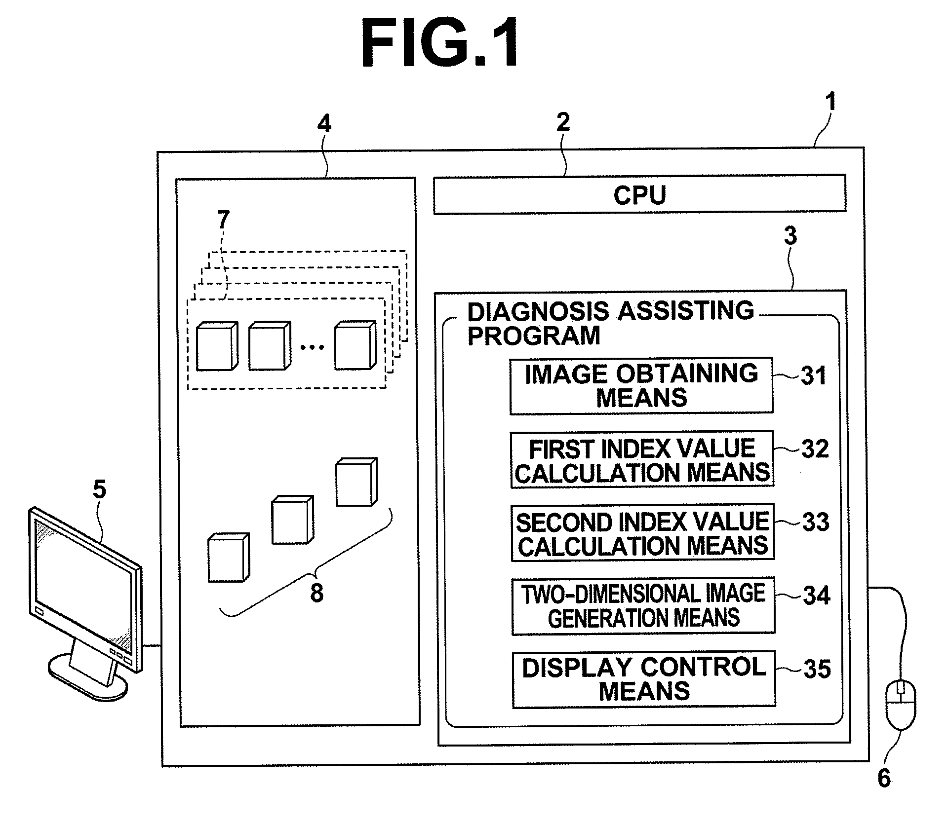
[0059]In each embodiment to be described herein below, diagnosis assisting apparatus 1 includes one computer on which a diagnosis assisting program of each embodiment is installed. The computer may be a workstation or a personal computer directly operated by a doctor who performs diagnosis, or it may be a server computer linked to the workstation or personal computer via a network. The diagnosis assisting program is stored in a recording medium, such as DVD, CD-ROM, or the like, and distributed, which is then installed on the computer from the recording medium. Alternatively, the program is stored in a storage device of a server computer linked to a network or in a network storage in a manner accessible from outside, then the program is down loaded and installed ...


PUM


Abstract

A diagnosis assisting apparatus, method, and program include calculating a first index value representing a direction and magnitude of motion of each portion of the heart for a three-dimensional anatomical image at a given phase of a three-dimensional anatomical image group representing a heart at each phase with respect to a further phase, calculating a second index value that serves as a diagnostic indicator of each portion of the heart from the three-dimensional anatomical image at the given phase or the three-dimensional anatomical image group, generating a two-dimensional image of the entire heart in which the second index value of each portion of the heart is disposed in a planar fashion, and displaying a mark representing the first index value superimposed on the generated two-dimensional image in a manner that allows the direction of motion of the first index value to be visually recognized.

Description

BACKGROUND OF THE INVENTION[0001]1. Field of the Invention[0002]The present invention relates to an apparatus, method, and computer program for assisting diagnosis by displaying cardiac motion in a two-dimensional image representing cardiac function calculated from three-dimensional image data.[0003]2. Description of the Related Art[0004]As a device for assisting a radiologist in performing image diagnosis, an apparatus that analyzes a state or motion of an organ of a subject based on three-dimensional data obtained by imaging the subject and displays analysis results on a screen in a manner appropriate for diagnosis is provided. As for the function to analyze cardiac beat motion, a function that calculates evaluation values of cardiac function (myocardial wall motion, wall thickness variation, and the like) based on time series three-dimensional data is known. A plurality of cross-sections perpendicular to an axis passing through the cardiac base (where a blood vessel is connected ...

Claims


Application Information

Patent Timeline
Patent Type & Authority Applications(United States)
IPC IPC(8): A61B6/00
CPCG06T2207/30048G06T11/206G06T7/0016G06T2207/20221G06T2200/24G06T2207/10072G06T7/20A61B5/055A61B6/503A61B6/5217A61B6/5235G01R33/481G01R33/5608
Inventor MIZUNO, OSAMU
Owner FUJIFILM CORP
Learn More