Cutting Tool

a cutting tool and tool body technology, applied in the field of cutting tools, can solve the problems of inefficiency of the cutting process, inconvenient and unnecessarily laborious second cutting step, and inability to clean the two-step cutting process, so as to facilitate the user in the cutting of curved lines

Inactive Publication Date: 2012-04-19
BPB LTD
View PDF16 Cites 6 Cited by
  • Summary
  • Abstract
  • Description
  • Claims
  • Application Information

AI Technical Summary

Benefits of technology

[0042]The cutting device may also comprise cutting aids in the form of a series of curved guide lines on a top surface of the upper part of the cutting device which facilitates a user in the cutting of curved lines.
[0043]The cu

Problems solved by technology

However, such a technique is inefficient due to a two-step cutting process being required.
The second cutting step can prove to be awkward and unnecessarily strenuous as it is usually necessary to try and cut the paper-like layer on the rear side from below the plasterboard.
Such a two-step cutting process is also not a clean process and leads to unnecessary dust and debris being created.
An unsatisfactory cut may also be obtained as it is difficult to perform the second cutting step exactly in line with the cut formed in the first cutting step.
However, with such techniques it is difficult to cut out sections from within board material such

Method used


Image

  • Cutting Tool
  • Cutting Tool
  • Cutting Tool

Examples


Embodiment Construction

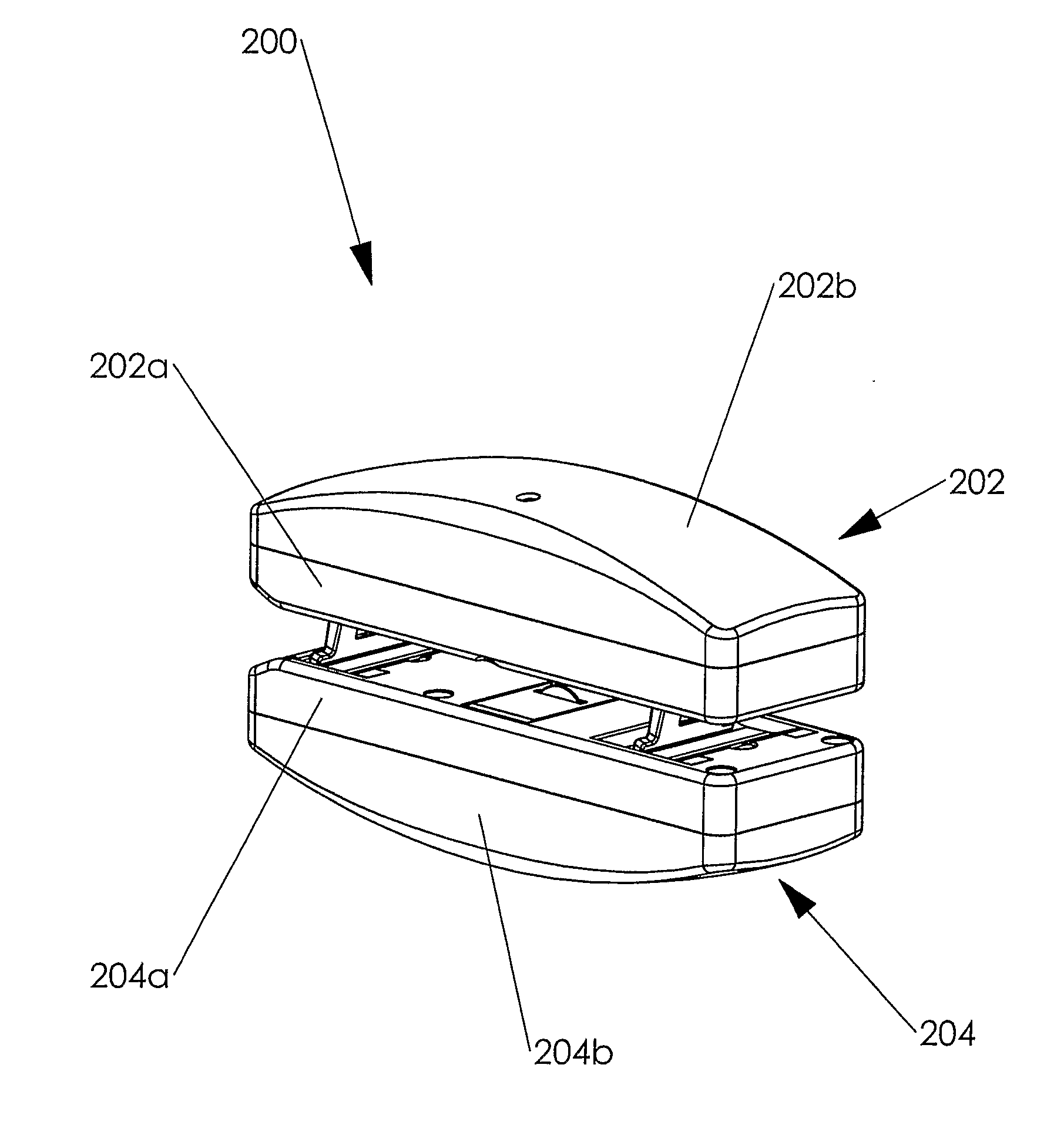
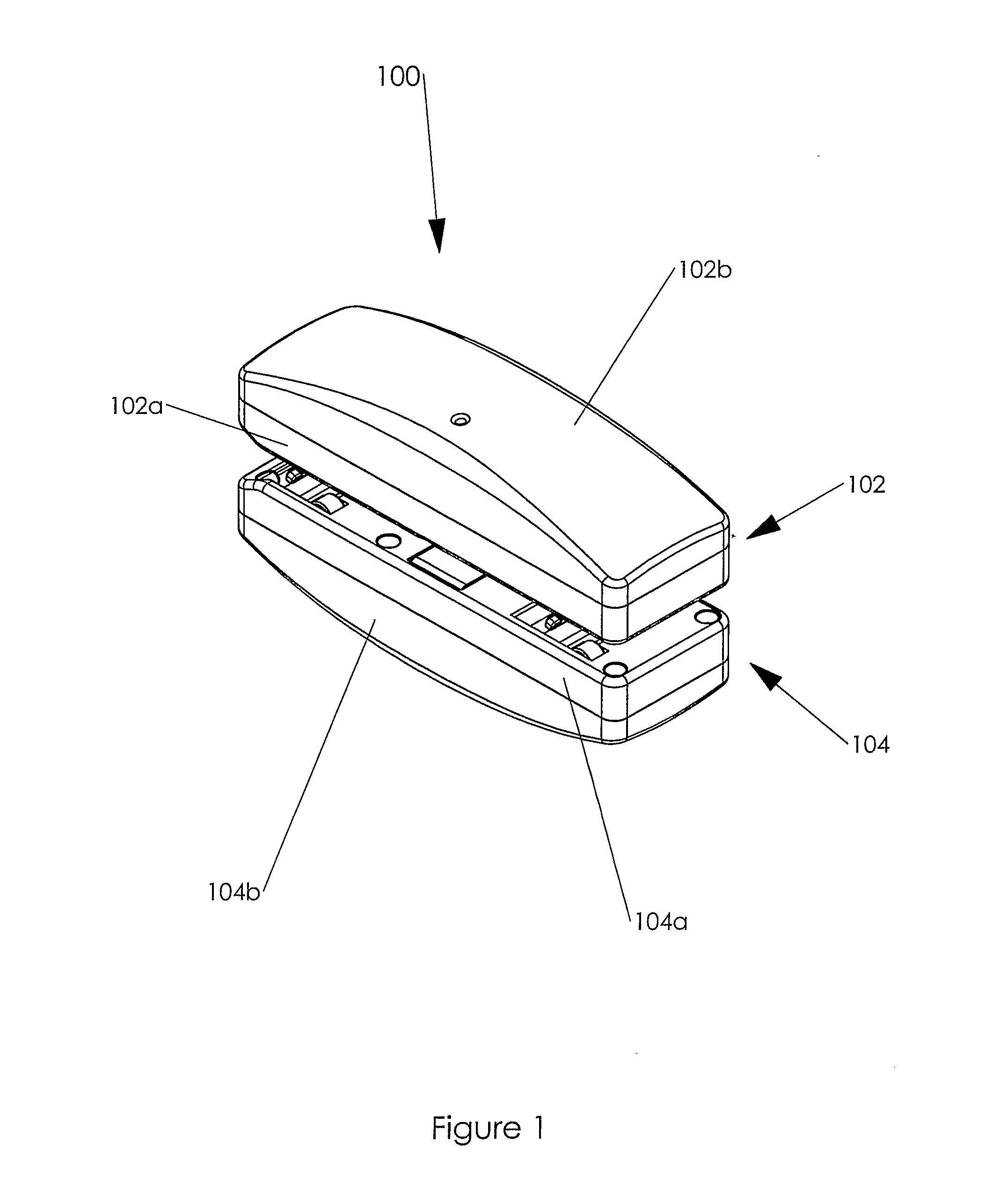
[0075]Referring to FIG. 1, there is a representation of a cutting tool according to the present invention, generally designated 100. The cutting tool 100 comprises two main body parts, namely, an upper part 102 and a lower part 104.

[0076]The upper part 102 of the cutting tool comprises a main body section 102a and an outer casing 102b. Similarly, the lower part 104 of the cutting tool 100 comprises a main body section 104a and an outer casing 104b.

[0077]Although not shown in FIG. 1, the upper part 102 of the cutting tool 100 may be shaped to conform with that of a hand to facilitate the application of pressure and therefore the use of the cutting tool 100.

[0078]The upper and lower parts 102,104 are moulded from plastics material using any suitable technique known in the art.

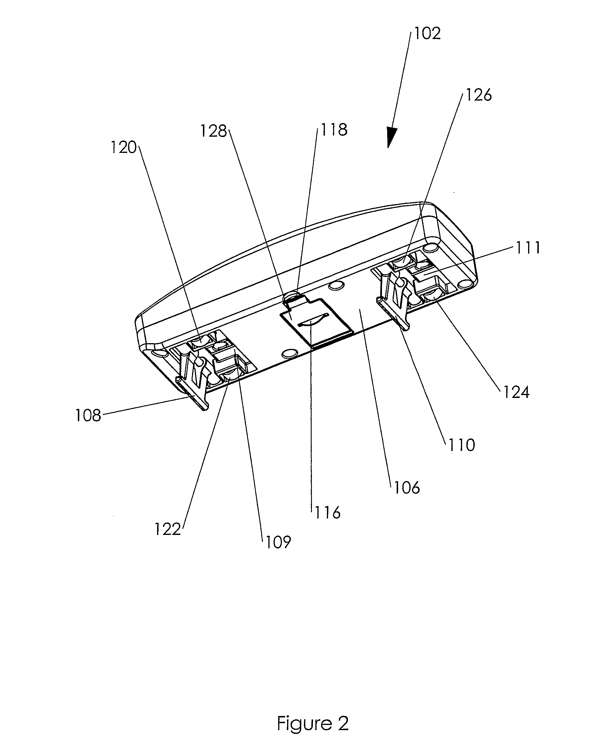
[0079]FIG. 2 is a representation of the underside 106 of the top part 102 of the cutting tool 100. On the underside 106, there are two separating arms 108,110. The separating arms 108,110 are mounted on axles 11...


PUM

PropertyMeasurementUnit
Depthaaaaaaaaaa
Magnetismaaaaaaaaaa

Abstract

There is provided a cutting tool (100) which is capable of performing cutting operations on a variety of materials such as, for example, plasterboard, glass, wood, laminated wood, cardboard, Perspex (Trade Mark), tiles, plastics or the like. The cutting tool (100) comprises an upper and lower part (102,104), said upper and lower parts (102,104) being separated by spacing means which are preferably retractable, the upper and lower parts (102,104) comprising at least one cutting device (116), and wherein the upper and lower parts (102,104) are held together with magnetic attraction.

Description

FIELD OF THE INVENTION[0001]This invention relates to a cutting tool. In particular, the present invention relates to a cutting tool which is capable of performing cutting operations on a variety of materials such as, for example, plasterboard.BACKGROUND OF THE INVENTION[0002]Plasterboard comprises a core of aerated gypsum plaster sandwiched between two sheets of tough paper or card. In the United Kingdom where homes are almost always constructed from brick and mortar, plasterboard is used mainly for lining internal walls or ceilings and for building partition walls. In the United States, plasterboard which is commonly known as wallboard or drywall, is often used to construct entire homes due to outer walls routinely being made from wood.[0003]To cut plasterboard, it is common to use a knife such as a Stanley Knife (Trade Mark) to cut along a pre-marked pencil line. However, such a technique is inefficient due to a two-step cutting process being required. In the first cutting step, ...

Claims


Application Information

Patent Timeline
IPC IPC(8): B26B25/00B26B3/08B26D3/08B26B5/00B26D1/14B26D7/20B28D1/22C03B33/12
CPCB26B3/08B26B5/005B26B25/00C03B33/12B26D3/085B26D7/20B28D1/225B26D1/141Y10T83/04Y10T83/0341Y10T83/667B23K26/38B26D3/08B28D1/22
Inventor CADDEN, STEPHENWALLACE, CAMPBELLLALL, MANJITNELSON, KENCHATTERS, STEVE
Owner BPB LTD
Why Eureka
Try Eureka