Electrically boosted braking system

a technology of braking system and electric boost, which is applied in the field of braking system, can solve problems such as complicated fitting and braking system, and achieve the effect of reducing the load on switching

Active Publication Date: 2012-04-19
ROBERT BOSCH GMBH
View PDF8 Cites 15 Cited by
  • Summary
  • Abstract
  • Description
  • Claims
  • Application Information

AI Technical Summary

Benefits of technology

[0018]In general, the use of the through-bolts as guide pins and the two return springs, which apply a reduced load to the actuator piston, means that the actuator piston can operate perfectly smoothly via its slideway connection with the guide

Problems solved by technology

Braking systems having a master cylinder boosted by an electric brake booster with an in-line ball screw are known but these braking systems have the disadvantage, because

Method used


Image

  • Electrically boosted braking system
  • Electrically boosted braking system
  • Electrically boosted braking system

Examples


Embodiment Construction

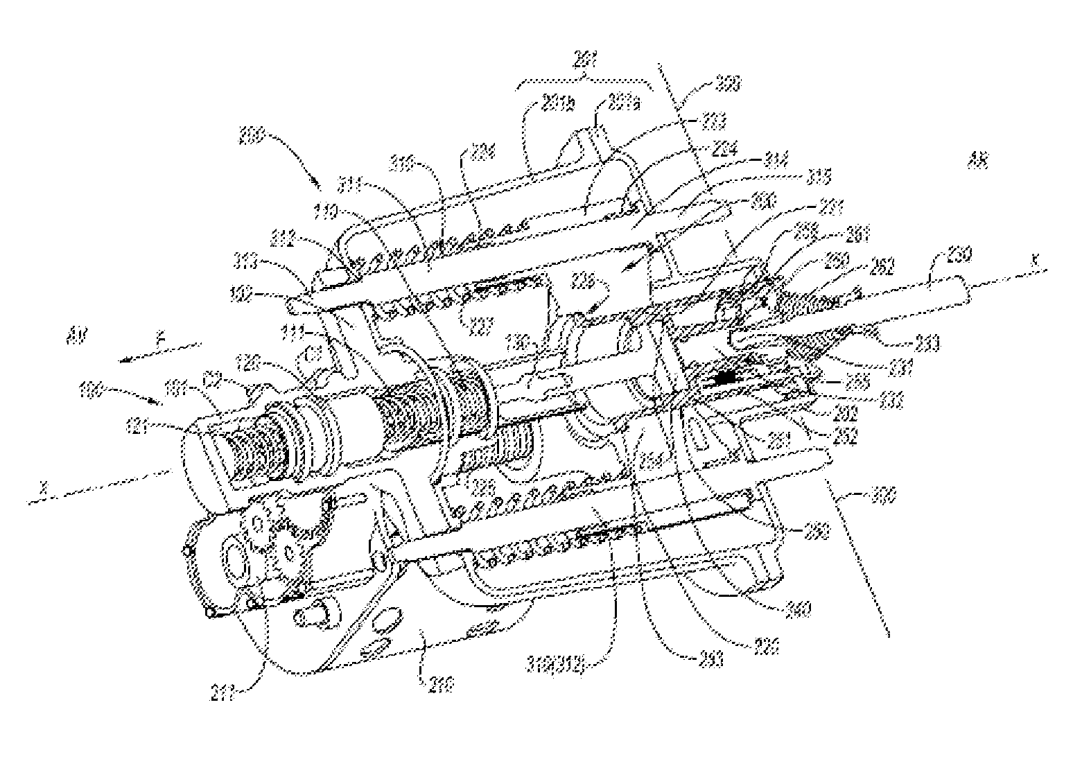
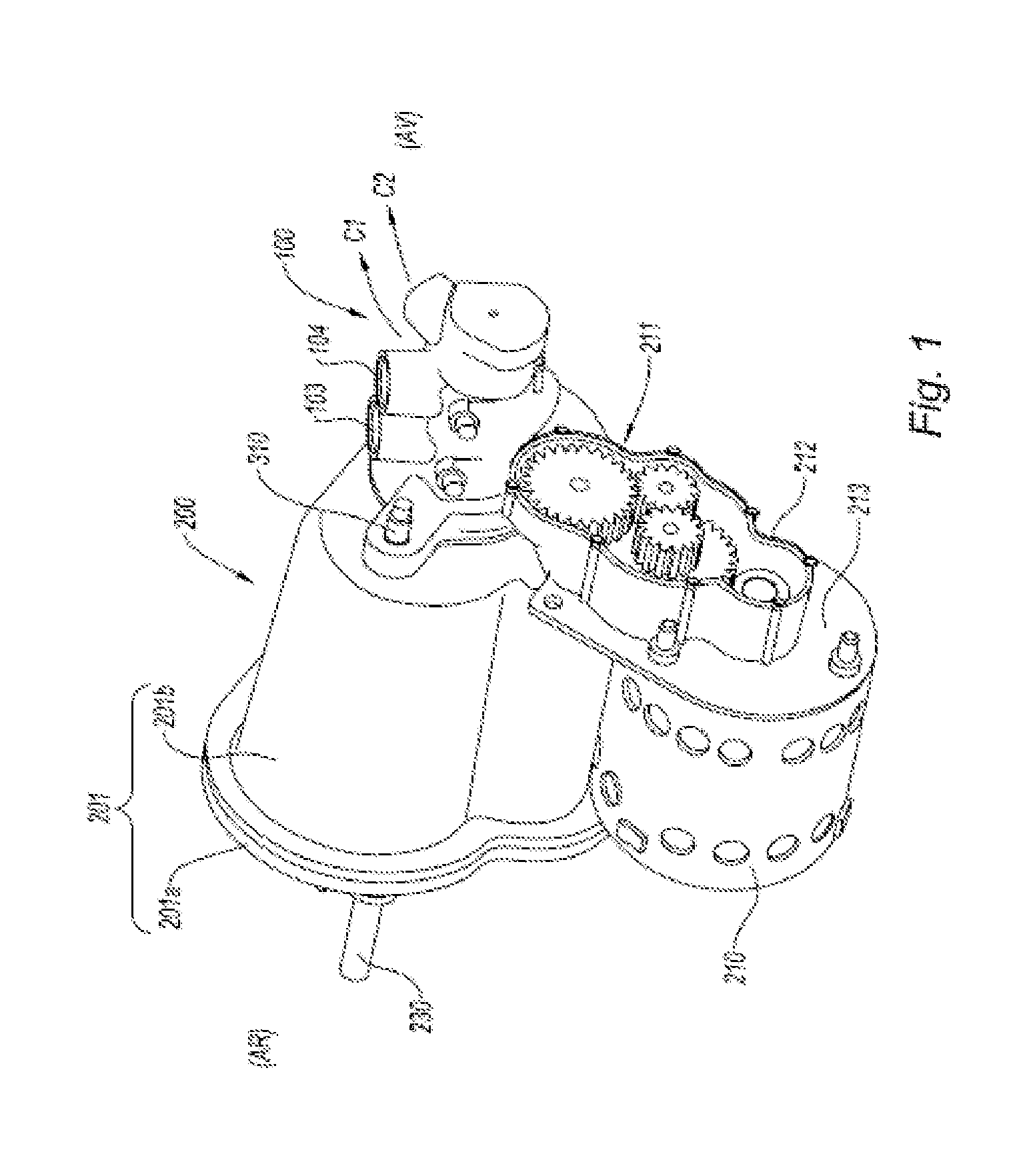
[0027]According to FIGS. 1 and 2, the braking system with a master cylinder boosted by an electric brake booster is made up of a master cylinder 100 connected to an electric brake booster 200 equipped with an actuator made up of an electric motor 210 and of reduction gearing 211 controlling the translational movement of the actuator piston 220 housed in a casing 201 and acting on the master cylinder 100 in the direction of braking (F). The master cylinder 100 in this instance is a tandem master cylinder of which the casing 101 comprises two inlets 103, 104 (FIG. 5) in its upper part to accept the two outlets from the brake fluid reservoir. On the side, the two chambers 111, 121, one of them delimited by the primary piston 110 and the other by the secondary piston 120, are connected to the two brake circuits C1, C2. The cups (seals) associated with the two pistons and the secondary piston and the springs are depicted in relief beyond the plane of section in FIG. 2.

[0028]By convention...


PUM


Abstract

Braking system comprising a brake booster (200) with electric motor driving the push rod (130) of the piston of the master cylinder (100) via a ball-screw connection and actuated by a control rod (230).
In the casing (201) connected to the master cylinder (100), the brake booster (200) comprises an actuator piston (220) guided in translational movement by at least two guide pins (311) which are parallel to the axis (XX) of the master cylinder (100) and which is driven in translational movement by a ball screw (225, 226) of which the screw (225), driven by the motor (210), is offset with respect to the axis (XX) of the master cylinder (100). The screw collaborates with a nut (226) translationally as one with the actuator piston (220), and a bore (221) of the actuator piston (220) receives a boost piston (250) equipped with a reaction disc (240) and with a plunger piston (232) connected to the control rod (230).

Description

BACKGROUND OF THE INVENTION[0001]The present invention relates to a braking system comprising a brake booster with electric motor driving the push rod of the piston of the master cylinder via a ball-screw connection and actuated by a control rod.[0002]Braking systems having a master cylinder boosted by an electric brake booster with an in-line ball screw are known but these braking systems have the disadvantage, because of the boost piston, of having a relatively large diameter and therefore of being expensive because of the size of the ball screw. In addition, they are complicated to fit.SUMMARY OF THE INVENTION[0003]It is an object of the present invention to develop a simple electrically boosted braking system that makes it possible to reduce the cost of manufacture and facilitate operation of the system in a booster failure mode in order to reduce the force that has to be applied in order to brake in the event of booster failure.[0004]To this end, the present invention relates t...

Claims


Application Information

Patent Timeline
IPC IPC(8): B60T13/74
CPCB60T13/745
Inventor PHILIPPE, RICHARDGAFFE, FRANCOISCAGNAC, BASTIEN
Owner ROBERT BOSCH GMBH
Why Eureka
Try Eureka