Fully Decoupled Hydraulic Torque Strut

a fully decoupled, hydraulic technology, applied in the direction of machine supports, shock absorbers, jet propulsion mounting, etc., to achieve the effect of minimal to no hydraulic damping and high hydraulic damping and stiffness

Inactive Publication Date: 2012-04-19
GM GLOBAL TECH OPERATIONS LLC
View PDF16 Cites 15 Cited by
  • Summary
  • Abstract
  • Description
  • Claims
  • Application Information

AI Technical Summary

Benefits of technology

[0013]The present invention packages a hydraulic device into a torque strut of a powertrain mounting system, for example a pendular mounting system, so as to provide high hydraulic damping and stiffness at high vibration amp

Problems solved by technology

Such devices are currently used in other configurations and under different load conditions, as for

Method used


Image

  • Fully Decoupled Hydraulic Torque Strut
  • Fully Decoupled Hydraulic Torque Strut
  • Fully Decoupled Hydraulic Torque Strut

Examples


Embodiment Construction

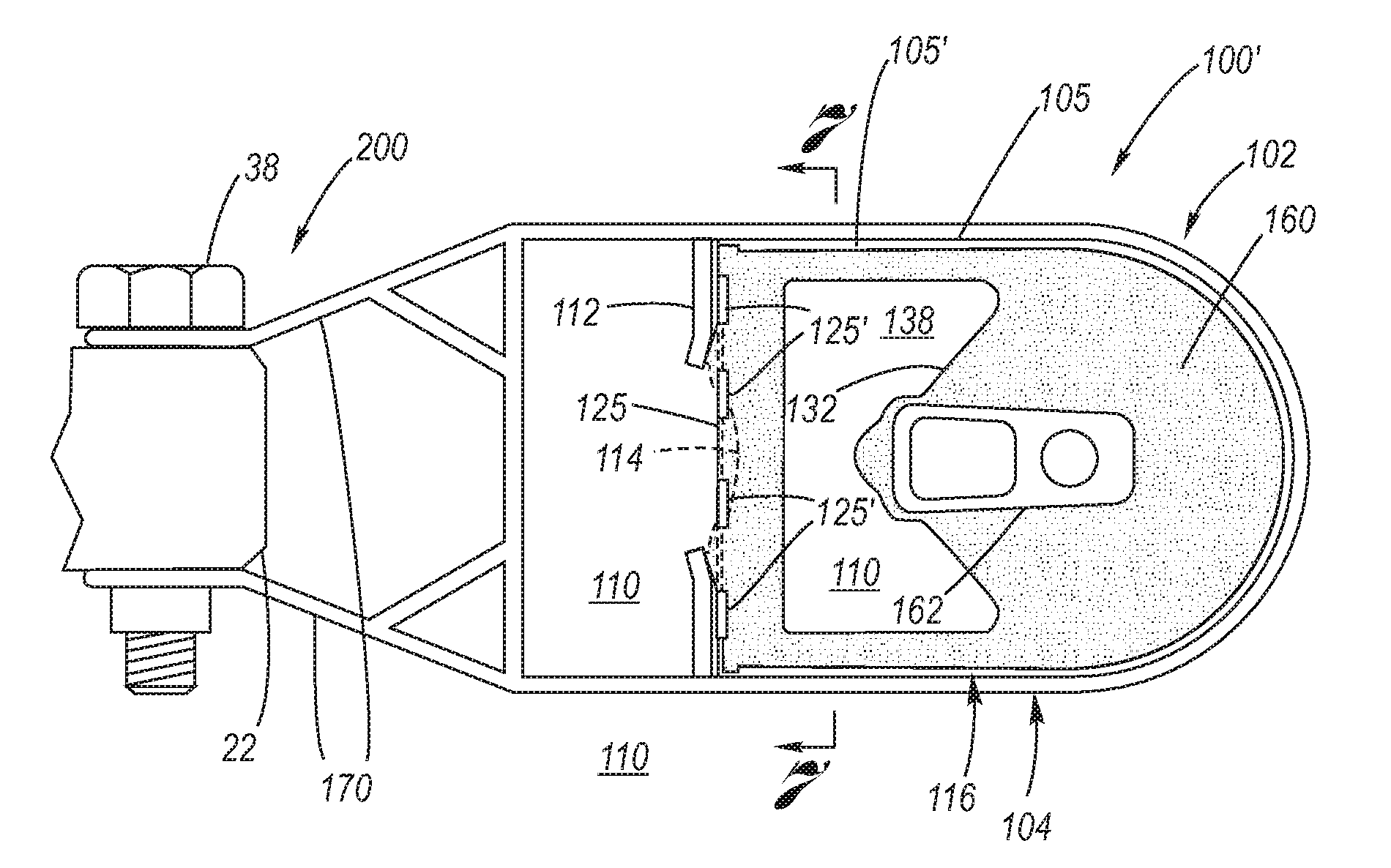
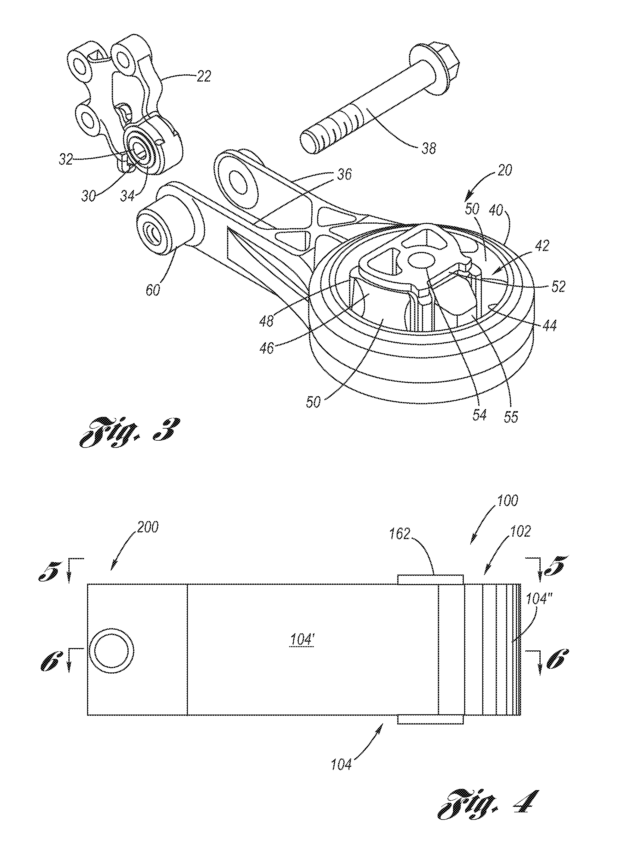
[0036]Referring now to the Drawings, aspects of a hydraulic device torque reacting mount bushing for a torque reacting hydraulic torque strut of a powertrain mounting system according to the present invention are depicted in FIGS. 4 through 14.

[0037]As shown at FIGS. 4 through 8, the hydraulic torque strut 100, 100′ according to the present invention has a head 102 having a U-shaped outer sleeve 104 composed of first and second parallel sleeve walls 104′ which are mutually and integrally connected at one end by a curvilinear sleeve wall 104″, and also composed of a complementarily shaped retainer wall 105 which is connected to the first and second sleeve walls and the curvilinear sleeve wall. At a distal disposition with respect to the curvilinear sleeve wall 104″, each of the first and second sleeve walls104′ has a mutually opposing stem wall 112 which support a bellows retainer 115 having an aperture 115′ formed therein whereat is disposed a bellows 114, whereby the bellows bridge...


PUM


Abstract

A hydraulic device disposed in a torque strut so as to provide a fully decoupled hydraulic torque strut. A main rubber element vibrates in response to powertrain pitch torque. At high vibration amplitude, high hydraulic damping is provided via a pumping chamber, an inertia track and a bellowed compensation chamber, wherein a decoupler system hydraulically connected to the pumping chamber is passively disabled. At low vibration amplitude, minimal hydraulic damping is provided via the decoupler system which is connected by a decoupler track to the compensation chamber.

Description

CROSS-REFERENCE TO RELATED APPLICATIONS[0001]The present application is a Continuation-in-Part of application Ser. No. 12 / 904,350, filed on Oct. 14, 2010, which application is presently pending.TECHNICAL FIELD[0002]The present invention relates to mounting systems used for mounting a powertrain in motor vehicle applications, particularly to pendular mounting systems, and more particularly to a fully decoupled pitch damping hydraulic torque strut at the torque strut mount thereof.BACKGROUND OF THE INVENTION[0003]Powertrain mounting systems used in motor vehicle applications include the “pendular” mounting system, exemplified at FIG. 1. In the pendular mounting system 10, there is included (dispositions being relative to forward travel direction 26 of the motor vehicle) a right-hand load bearing mount 12, a left-hand load bearing mount 14, and a (rear disposed) torque reacting strut mount 18, composed of a torque strut 20 and a torque strut bracket assembly 22. The two load bearing mo...

Claims


Application Information

Patent Timeline
IPC IPC(8): F16F13/06
CPCF16F13/10B60K5/1216
Inventor LEE, PINGGANNON, DANIEL G.
Owner GM GLOBAL TECH OPERATIONS LLC
Why Eureka
Try Eureka