Conductor wire for motor and coil for motor

Active Publication Date: 2012-04-19
TOYOTA JIDOSHA KK
View PDF4 Cites 18 Cited by
  • Summary
  • Abstract
  • Description
  • Claims
  • Application Information

AI Technical Summary

Benefits of technology

[0021]A conductor wire for motor and a coil for motor according to the pr

Problems solved by technology

This may increase eddy current loss.
This eddy current loss is power loss caused by the flow of eddy currents.
However, the outer peripheral surface of the bundle of fine wires is coated with resin and thus a coating part is low in strength.
For example, when a conductor wire is bent to form a co

Method used


Image

  • Conductor wire for motor and coil for motor
  • Conductor wire for motor and coil for motor
  • Conductor wire for motor and coil for motor

Examples


first embodiment

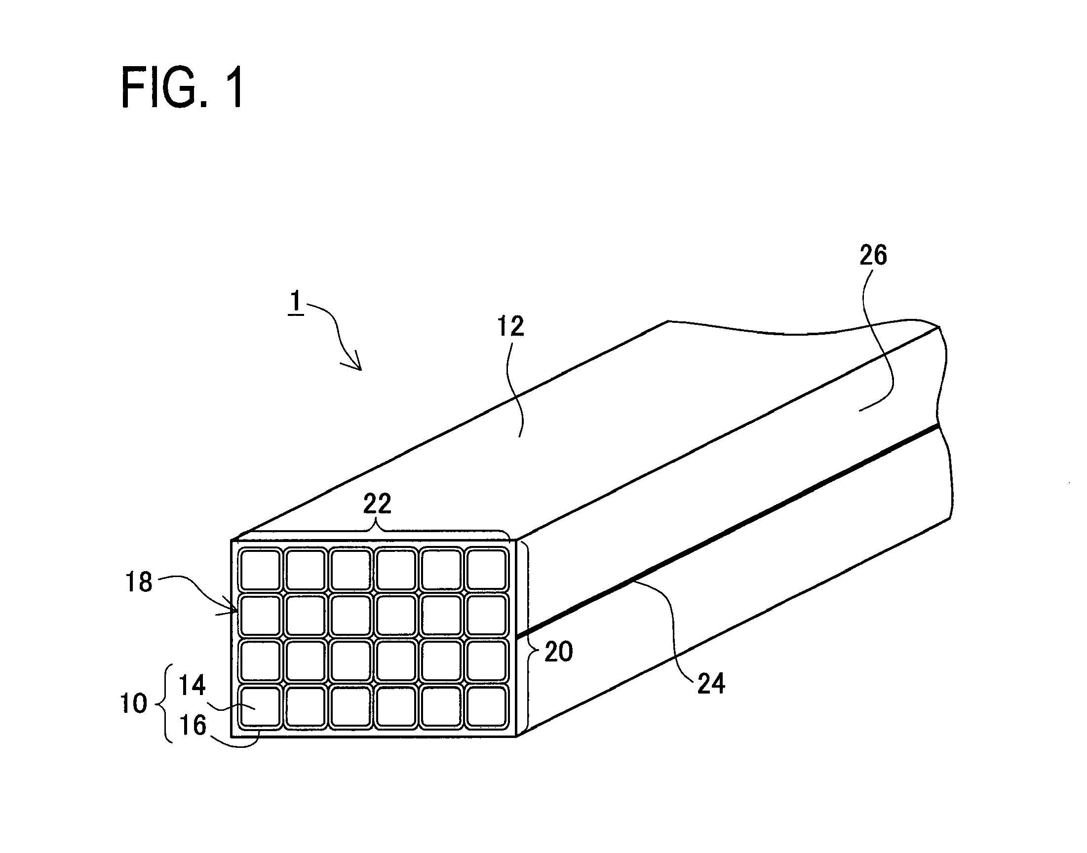
[0031]A flat conductor wire 1 in the first embodiment includes a plurality of fine wires 10 and a foil 12 as shown in FIG. 1. The foil 12 is an example of a “foil-shaped member”. For convenience of explanation, in FIG. 1, the flat conductor wire 1 is illustrated by omitting an insulating layer made of enamel resin or the like on an outer peripheral surface of the conductor wire 1 to ensure an insulating property.

[0032]Each fine wire 10 is formed of a core wire 14 provided with an insulating part 16 on an outer peripheral surface. The core wire 14 is a conductor made of conductive metal such as copper, aluminum (aluminium), silver, gold, or their alloys and shaped in a linear form. The insulating part 16 is made of enamel resin, metal oxide, or the like.

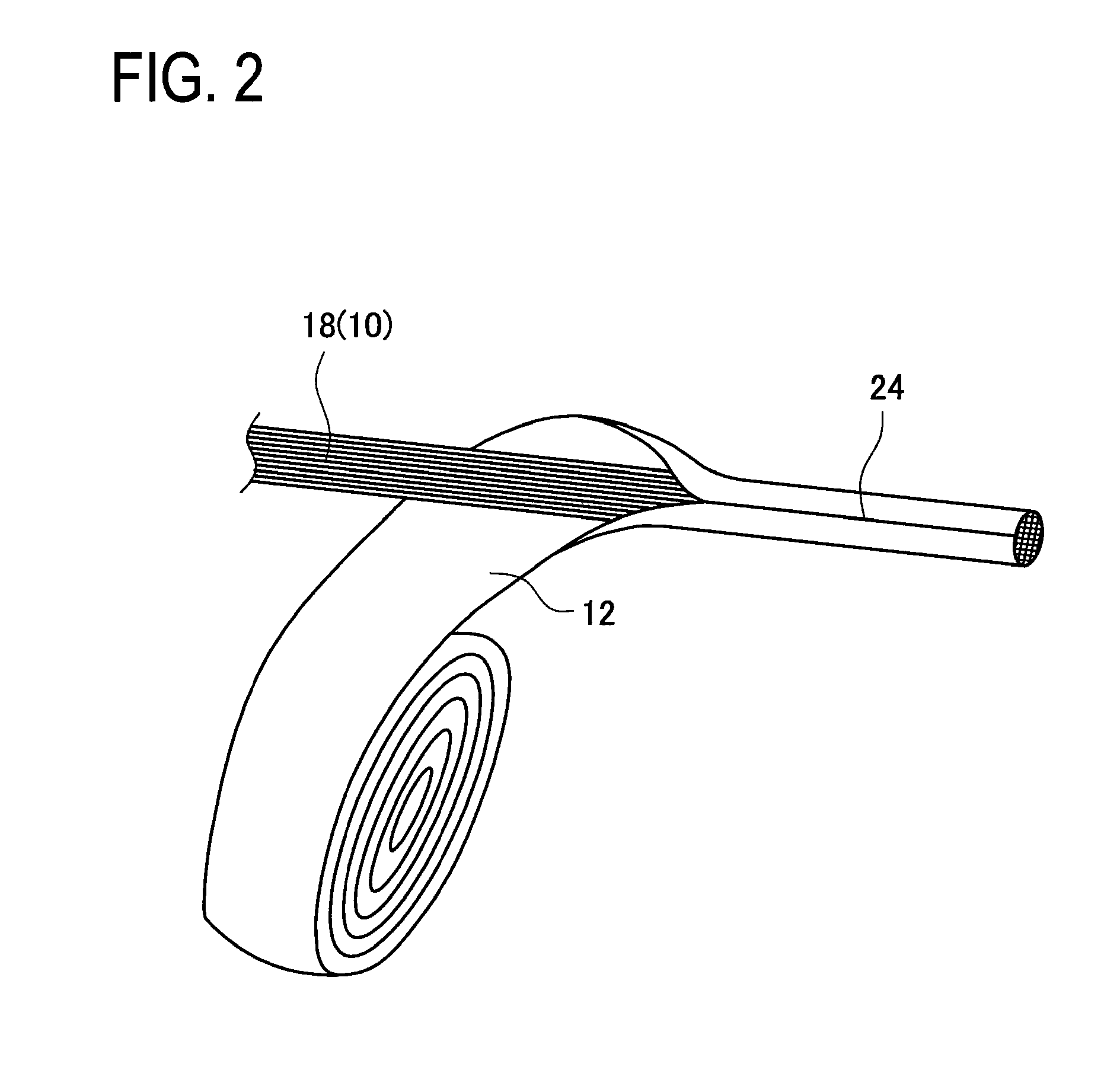
[0033]As shown in FIG. 1, the flat conductor wire 1 is formed of a fine wire assembly 18 including a plurality of fine wires 10 assembled in a bundle, and the foil 12 covering the outer peripheral surface of the fine wire assembly 18....

second embodiment

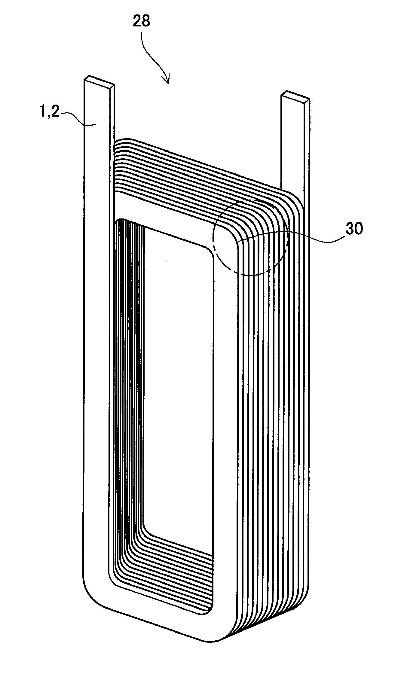
[0051]A flat conductor wire 2 in a second embodiment includes a plurality of fine wires 10, a tape 32, and others as shown in FIG. 5. The fine wires 10 are identical to those in the first embodiment. The flat conductor wire 2 is formed by spirally winding the tape 32 on the outer peripheral of a fine wire assembly 18 consisting of the fine wires 10 assembled in a bundle as shown in FIG. 5. The tape 32 is an example of a “strip member” of the invention. In the following explanation, similar or identical parts to those in the first embodiment are given the same reference signs and their details are not explained.

[0052]The tape 32 is made of the same metal as a core wire 14 of each fine wire 10 (i.e., a metal having the same electrical resistance value) or a metal having an electrical resistance value larger than the electrical resistance value of the core wires 14 of the fine wires 10. For instance, in the case where the material of the core wires 14 of the fine wires 10 is copper, th...


PUM


Abstract

The present application has a purpose to provide a conductor wire for motor capable of improving durability against bending, and a coil for motor using the conductor wire for motor. One aspect of the invention, therefore, provides a conductor wire for motor comprising a fine wire assembly and a coating member covering an outer peripheral surface of the fine wire assembly, the fine wire assembly consisting of a plurality of fine wires assembled in a bundle, and each of the fine wires including a conductor and an insulating part provided on an outer peripheral surface of the conductor, wherein the coating member is made of metal, and the coating member has an electrical resistance value larger than an electrical resistance value of the conductor.

Description

CROSS-REFERENCE TO RELATED APPLICATIONS[0001]This application is a continuation application based upon and claims the benefit of the prior PCT International Patent Application No. PCT / JP2010 / 068186 filed on Oct. 15, 2010, the entire contents of which are incorporated herein by reference.TECHNICAL FIELD[0002]The present invention relates to a conductor wire for motor including a plurality of electrically conductive fine or thin wires assembled in a bundle and a coil for motor including the conductor wire for motor.BACKGROUND ART[0003]A flat conductor wire is used as a wire forming a coil in order to enhance the space factor of the coil in a motor. The space factor in this description indicates a ratio of the cross-sectional area of a wire to the cross section of a space in which the coil is placed. However, the flat conductor wire has a large cross-sectional area. Thus, when the flat conductor wire is placed in an alternating magnetic field, large eddy currents tend to occur in a sur...

Claims


Application Information

Patent Timeline
IPC IPC(8): H01F27/28H01B7/00
CPCH02K3/42H01B5/14
Inventor URANO, HIROAKI
Owner TOYOTA JIDOSHA KK
Why Eureka
Try Eureka