Projection optical system and image projector

a technology which is applied in the field of projection optical system and image projector, can solve the problems of dust deposition, inability to use at a distance from the projection surface,

Active Publication Date: 2012-04-19
RICOH KK
View PDF2 Cites 31 Cited by
  • Summary
  • Abstract
  • Description
  • Claims
  • Application Information

AI Technical Summary

Problems solved by technology

Ultra short focus projectors have the advantage of letting a presenter make a presentation without the shadow of the presenter appearing on a projection surface, but have the disadvantage of not being usable at a distance from the projection surface and thus being required to be embedded in the projection surface if the projection distance is shorter than the overall length of the optical system.
In these projectors, if optical systems are exposed, there arises the problem of dust deposition or the like.

Method used


Image

  • Projection optical system and image projector
  • Projection optical system and image projector
  • Projection optical system and image projector

Examples


first embodiment

Second Variation of First Embodiment

[0063]In the first variation of the first embodiment, the case is illustrated where the second optical system 12 is divided by the nonlinear boundary 12c. In a second variation of the first embodiment, another case of dividing the second optical system 12 by the nonlinear boundary 12c is illustrated.

[0064]FIG. 7 is a diagram illustrating the second optical system 12 in a normal direction of the reflection region 12a according to the second variation of the first embodiment. In FIG. 7, the shape of an image at a time when rays of light that have passed through the first optical system 11 are made incident on the second optical system 12 is indicated by a broken line, and is referred to as “image shape 11x.”

[0065]Since the reflection region 12a of the second optical system 12 may have a shape corresponding to the image shape 11x, the boundary 12c between the reflection region 12a and the transmission region 12b may be curved along the image shape 11...

second embodiment

[0069]In the first embodiment, the case is illustrated where the second optical system 12 is planar (flat). In a second embodiment, a case of bending the second optical system is illustrated.

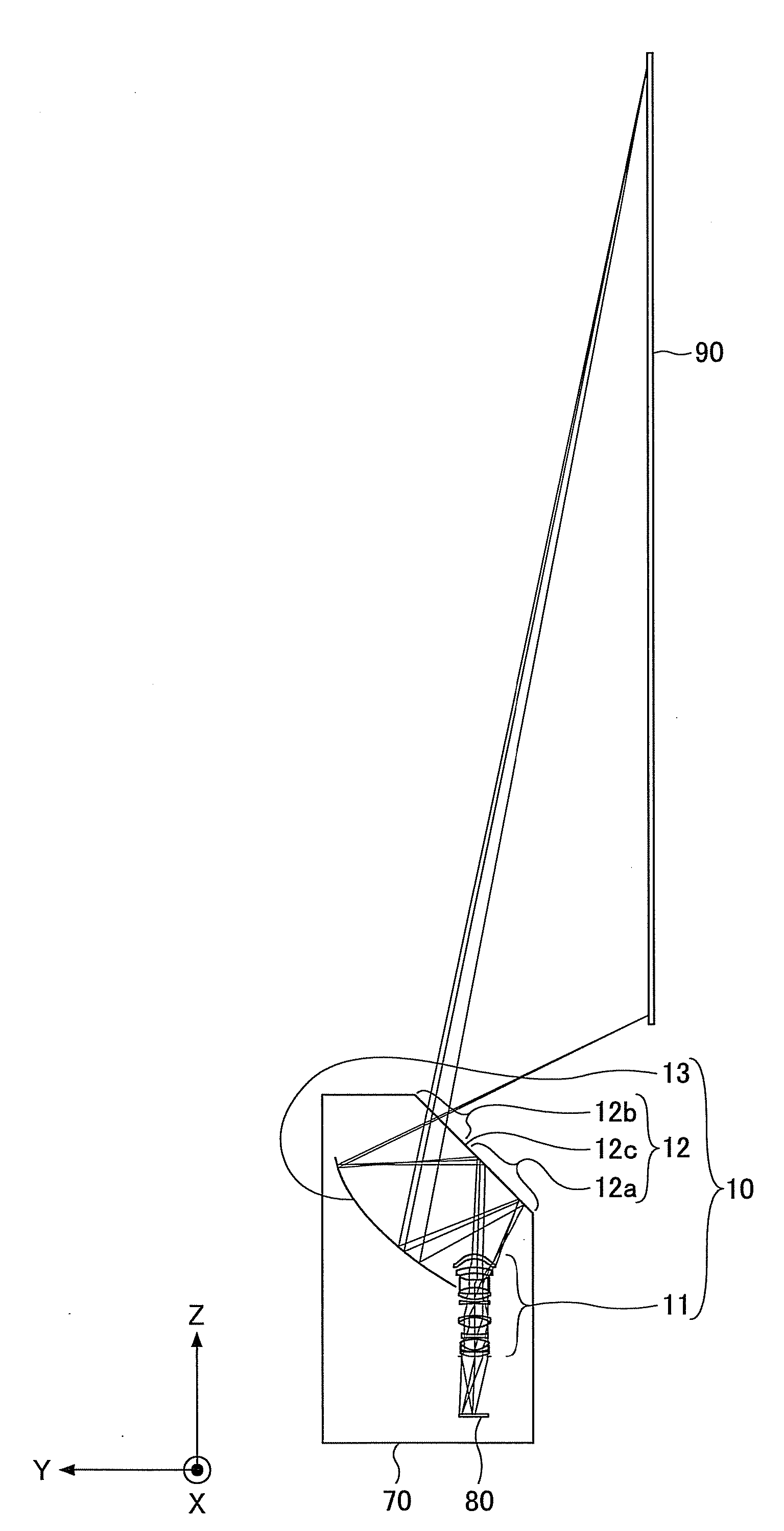
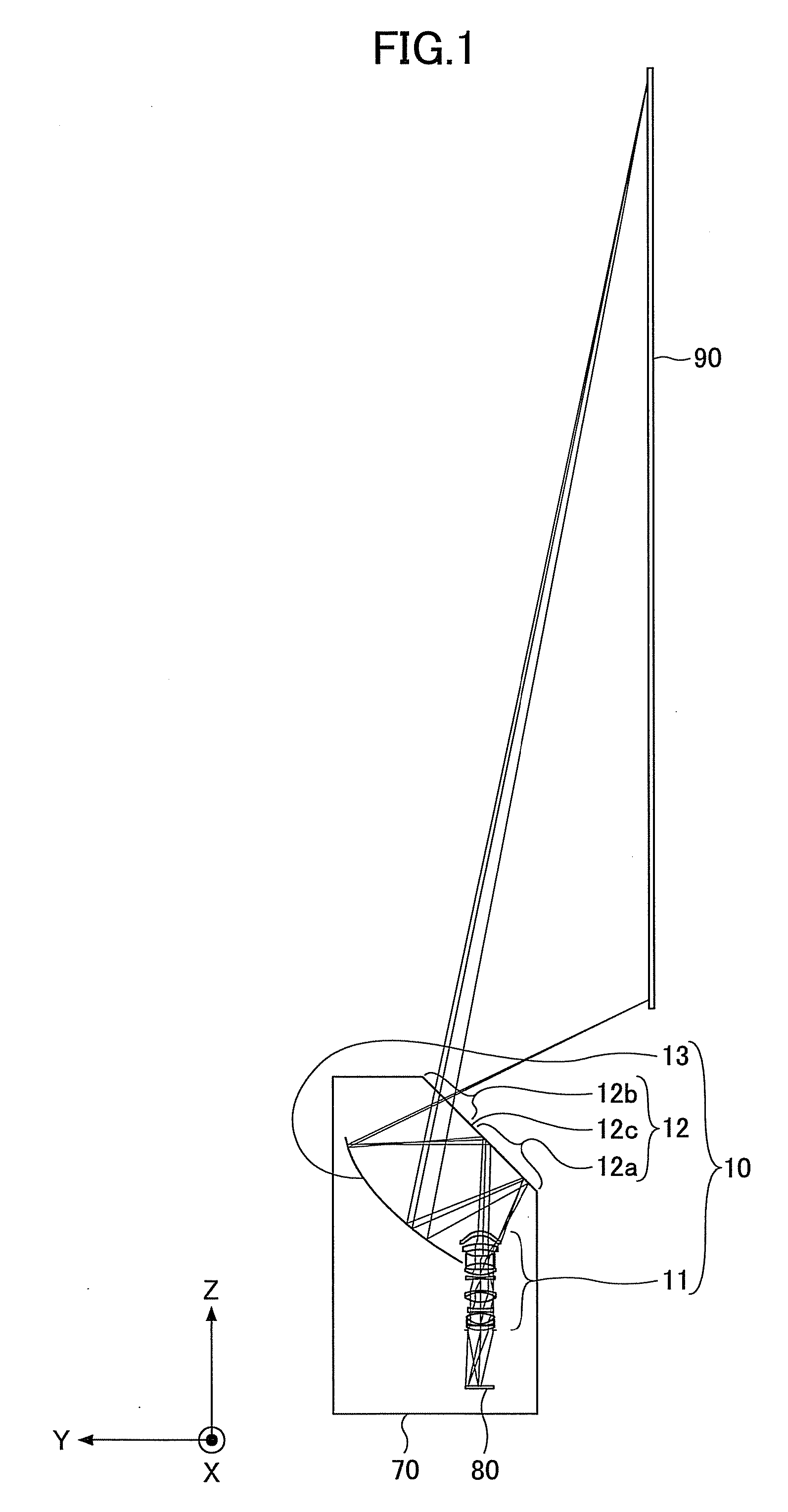
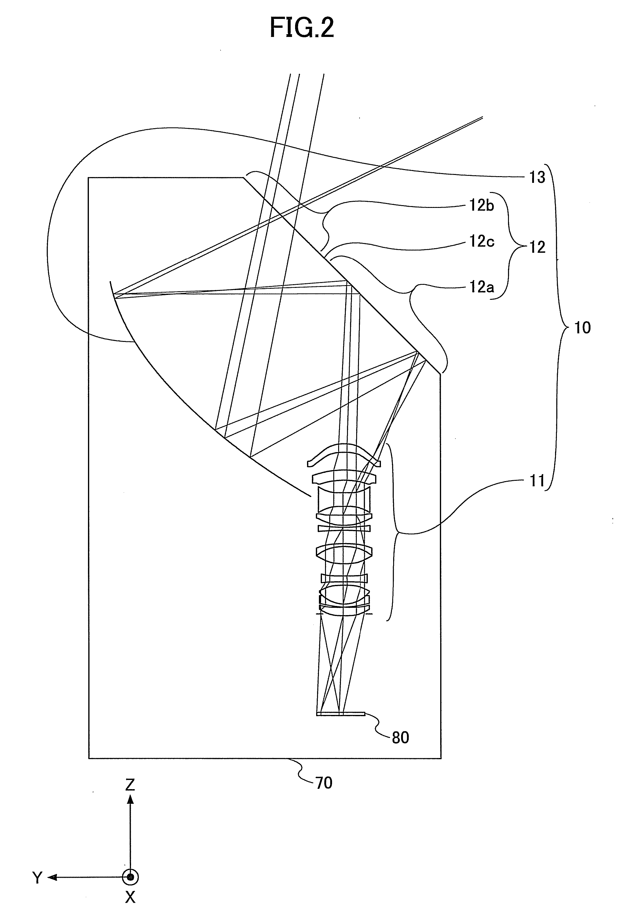
[0070]FIG. 9 is a ray diagram illustrating a projection optical system according to the second embodiment. FIG. 10 is an enlarged view of part of FIG. 9. In the coordinate system in FIG. 9 and FIG. 10, X, Y, and Z denote the long axis directions, the normal directions, and the short axis directions, respectively, of the screen 90.

[0071]Referring to FIG. 9 and FIG. 10, a projection optical system 20 is different from the projection optical system 10 (FIG. 1 and FIG. 2) in having a second optical system 22 that replaces the second optical system 12.

[0072]The second optical system 22 includes a reflection region 22a and a transmission region 22b. The second optical system 22 is so attached as to close the opening of the housing 70. The second optical system 22 is bent at a boundary 22c between the ...

third embodiment

[0083]In the first embodiment, the case is illustrated where the second optical system 12 is flat, and in the second embodiment, the case is illustrated where the second optical system 22 is bent. In a third embodiment, a case of tilting the transmission region toward a screen in the second embodiment is illustrated.

[0084]FIG. 15 is a ray diagram illustrating a projection optical system according to the third embodiment. FIG. 16 is an enlarged view of part of FIG. 15. In the coordinate system in FIG. 15 and FIG. 16, X, Y, and Z denote the long axis directions, the normal directions, and the short axis directions, respectively, of the screen 90.

[0085]Referring to FIG. 15 and FIG. 16, a projection optical system 30 is different from the projection optical system 20 (FIG. 6 and FIG. 10) in having a second optical system 32 that replaces the second optical system 22.

[0086]The second optical system 32 includes a reflection region 32a and a transmission region 32b. The second optical syst...


PUM


Abstract

A projection optical system configured to project an image onto a projection surface includes a first optical system including at least one dioptric system and having positive power as a whole; a second optical system including a reflection region and a transmission region; and a third optical system including at least one reflecting surface having power, and having positive power as a whole, wherein light entering the projection optical system passes through the first optical system to have a path thereof bent by the reflection region of the second optical system to be incident on the third optical system, and the light incident on the third optical system has the path thereof bent by the third optical system to pass through the transmission region of the second optical system to be incident on the projection surface.

Description

CROSS-REFERENCE TO RELATED APPLICATION[0001]The present application is based upon and claims the benefit of priority of Japanese Patent Application No. 2010-231951, filed on Oct. 14, 2010, the entire contents of which are incorporated herein by reference.BACKGROUND OF THE INVENTION[0002]1. Field of the Invention[0003]The present invention relates to a projection optical system and an image projector including the projection optical system.[0004]2. Description of the Related Art[0005]Recently, liquid crystal projectors, which are widely known as image projectors, have incorporated liquid crystal panels of higher resolution, have been improved in brightness with higher efficiency of light source lamps, and have been reduced in price. Further, small-size, light-weight image projectors using a digital micro-mirror device (DMD) or the like have been popular, so that image projectors have been widely used not only in offices or at school but also at home. In particular, front-type project...

Claims


Application Information

Patent Timeline
Patent Type & Authority Applications(United States)
IPC IPC(8): G03B21/14
CPCH04N9/3102G03B21/14G03B21/28
Inventor TAKAHASHI, TATSUYAFUJITA, KAZUHIROABE, ISSEI
Owner RICOH KK
Why Eureka
Try Eureka