Differential Vibratation Of Dental Plate

a differential vibrating and dental plate technology, applied in dental surgery, dental tools, medical science, etc., can solve the problems of cumbersome devices, high cost, and cumbersome design and construction, and achieve the effect of reducing cost and simplifying design and manufactur

Active Publication Date: 2012-04-19
ADVANCED ORTHODONTICS & EDUCATION ASSOC LLC
View PDF8 Cites 24 Cited by
  • Summary
  • Abstract
  • Description
  • Claims
  • Application Information

AI Technical Summary

Benefits of technology

[0018]This invention continues the work described in U.S. application Ser. Nos. 11 / 773,849, 11 / 773,858, and 61 / 040,777 incorporated herein by reference, but presents an improvement thereon that allows the treatment of an individual tooth or groups of teeth. The prior inventions were generally based on vibrating the entire dentition, which allows for the motor (and battery) to be placed externally, thus simplifying the design and manufacture and reducing cost. However, there are instances where it would be desirable to target a single tooth or a group of teeth for treatment, without vibrating the entire dental plate.

Problems solved by technology

Although effective, this widely accepted approach takes about twenty four months on average to achieve success.
The devices are cumbersome, difficult to construct, expensive and are very difficult to use, thus reducing patient compliance.
Further, the dental plate is brass, and is very unpleasant to bite on.
Most importantly, there is no recognition in either patent that the vibratory device can be used for tooth remodeling or movement.
Thus, the shape of the dental plate in each case is a very flat U- or Y-shaped member that is largely ineffective for remodeling.
Additionally, the vibration is not optimized in frequency and amplitude for remodeling.
Finally, neither device is programmable, nor can teeth be differentially vibrated, thus the dentist cannot optimize its usage for each patient, nor monitor patient compliance.
All of these shortcomings reduce the effectiveness of these devices for remodeling uses.
U.S. Pat. No. 6,632,088 describes a bracket with powered actuator mounted thereto to provide vibration, but this device appears to also be held completely internally to the patients mouth, thus again being cumbersome, and thus may affect patient comfort and ultimately patient acceptance of the device.
Therefore, the device is uncomfortable for the patent to use, and there is always some risk of electric shock.
This device is only used with an implant, and does not appear suitable for general orthodontic use.

Method used


Image

  • Differential Vibratation Of Dental Plate
  • Differential Vibratation Of Dental Plate
  • Differential Vibratation Of Dental Plate

Examples


example 1

Differential Vibrational Dental Plate

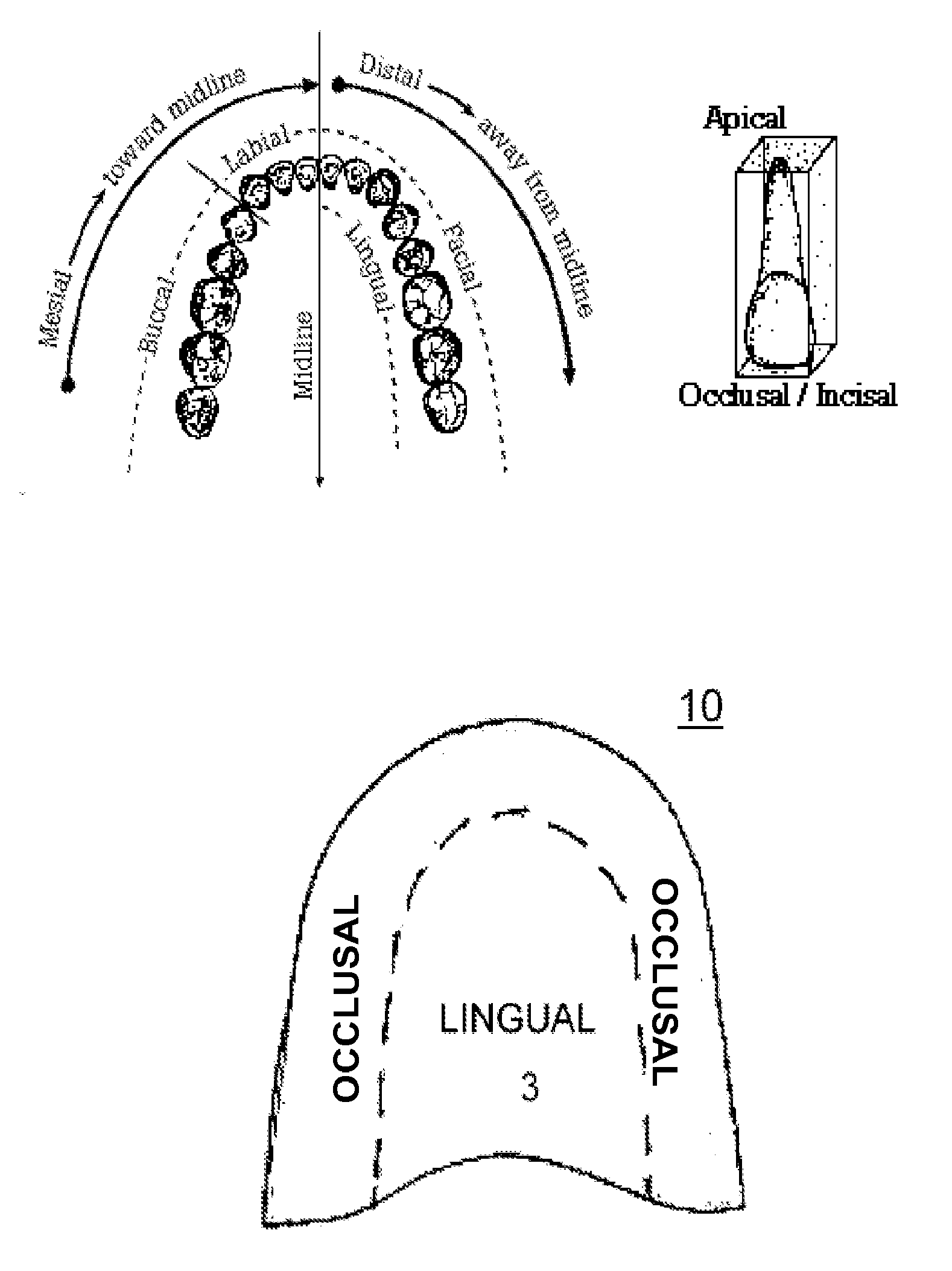
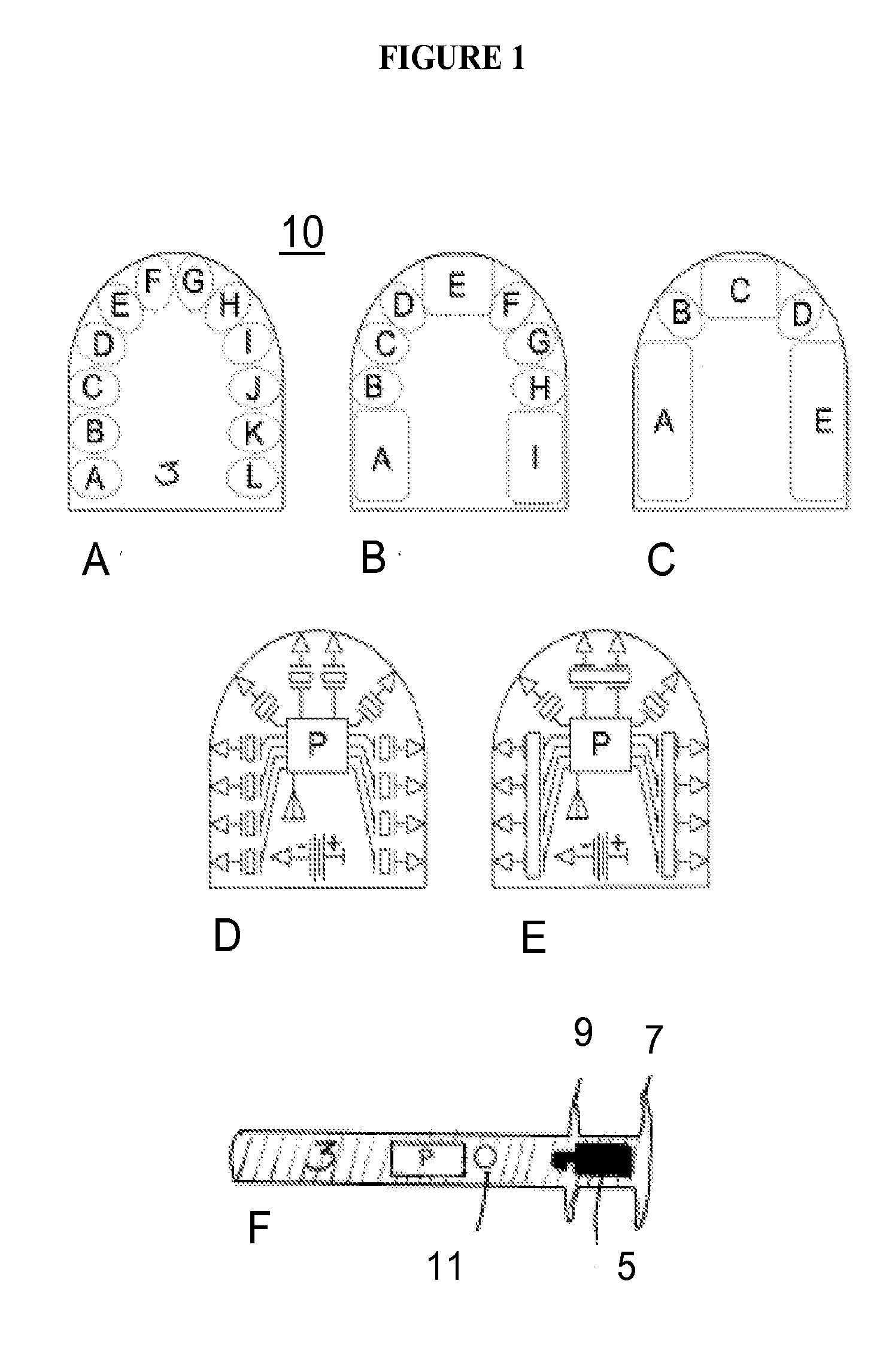
[0044]FIG. 1 shows one embodiment of a differential vibration dental plate 10. The device 10 has an intraoral bite plate 3 that lingually shaped for insertion into a patient's mouth. Inside the bite plate 3 are tiny vibration motors (A-L) situated to contact the various tooth zones. Alternatively, a continuous piezoelectric motor can differentially apply vibrational force to the various zones.

[0045]The device 10 is clamped down by the patient's jaw on the bite plate 3 to secure it between the dental arches. The vibration sources A-L in this embodiment are activated by pushing a button (not shown) on the bite plate, or alternatively can be activated by patient bite pressure thus closing the relevant circuit.

[0046]The bite plate is covered with a polymeric molded coating (not shown) or housing (not shown) in order to hermetically seal the motors. An access valve (not shown) can provide access for replacement of the batter (P).

[0047]Using a continuo...

example 2

Customizable Differential Vibrational Dental Plate

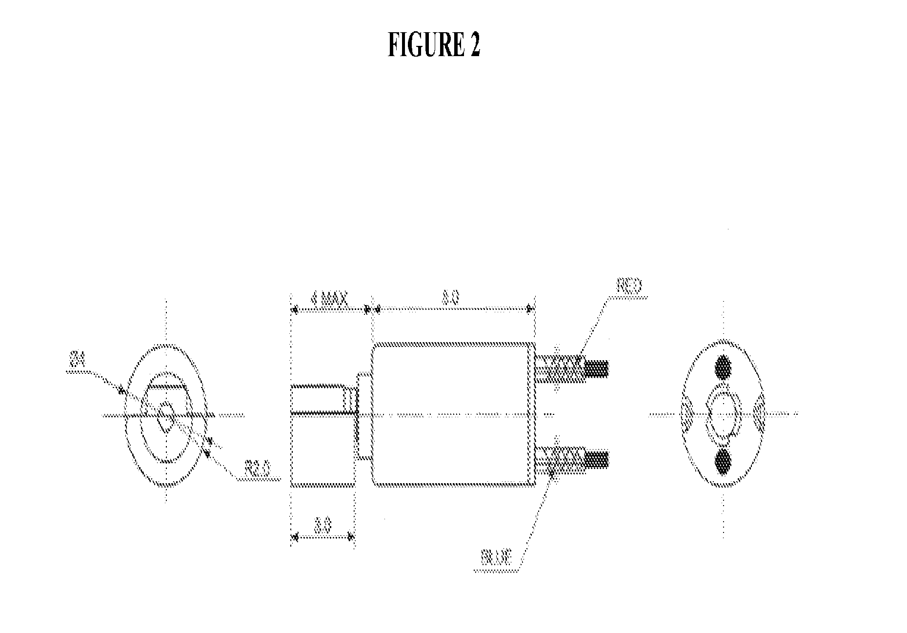
[0050]The embodiment described in Example 1 has vibration motors at all quadrants of the bite plate, and relies on differential programming or activation to achieve differential vibration. However, this embodiment has two disadvantages, namely, cost increases because each vibration motor and the associated circuitry contribute to cost. Secondly, since the bite plate covers all of the teeth, there is some transmission of vibration from the activated motors to other teeth. This embodiment solves these two difficulties by having a universal dental guide as opposed to dental plate, that is a U-shaped wire or band that fits on the facial surface of the teeth, and to which one or more vibration motors can be placed and affixed at the desired location (see FIG. 2B).

[0051]Preferably the dental guide is made of metal or other slightly deformable material, so that the curvature of the dental guide can be adjusted for each patient. However, if ...


PUM


Abstract

An improved vibrating dental plate that allows differential vibration of one or more teeth to assist in orthodontic remodeling is provided.

Description

CROSS REFERENCE TO RELATED APPLICATIONS[0001]This application claims priority to U.S. Provisional Application 61 / 074,884, filed Jun. 23, 2008, incorporated by reference.FEDERALLY SPONSORED RESEARCH STATEMENT[0002]Not applicable.REFERENCE TO MICROFICHE APPENDIX[0003]Not applicable.FIELD OF THE INVENTION[0004]The invention relates to systems and methods for correcting malocclusion, and in particular to a device that corrects occlusion via the differential vibration of one or more teeth.BACKGROUND OF THE INVENTION[0005]Orthodontics is a dental specialty that treats malocclusion through the movement of teeth as well as control and modification of facial growth. This process is usually accomplished by using a continuous mechanical force to induce bone remodeling, thereby enabling the teeth to move to a better position. In this approach, orthodontic appliances provide a continuous static force to the teeth via an archwire connected to brackets affixed to each tooth. As the teeth slowly mo...

Claims


Application Information

Patent Timeline
Patent Type & Authority Applications(United States)
IPC IPC(8): A61C7/08
CPCA61C7/08A61C7/00A61C7/008
Inventor PAVLIN, DUBRAVKO
Owner ADVANCED ORTHODONTICS & EDUCATION ASSOC LLC
Why Eureka
Try Eureka