Ultrasound diagnostic apparatus

a diagnostic apparatus and ultrasound technology, applied in the field of ultrasound diagnostic equipment, can solve the problems of reducing the capability of imaging the needle on the ultrasound image, and the inability to significantly reduce the insertion angl

Inactive Publication Date: 2012-04-19
FUJIFILM CORP
View PDF6 Cites 8 Cited by
  • Summary
  • Abstract
  • Description
  • Claims
  • Application Information

AI Technical Summary

Benefits of technology

[0008]In paracentesis, thinner needles reduce patient burdens and invasiveness and therefore the smallest possible puncture needle is selected in consideration of the risk or the like. However, the thinner the needle is, the more the capability of imaging the needle on the ultrasound image is reduced. The needle is imaged discontinuously and the position or the shape of the puncture needle cannot be clearly displayed.
[0015]An object of the present invention is to solve the foregoing prior art problems and to provide an ultrasound diagnostic apparatus which ensures that a puncture needle inserted from a position away from an ultrasound probe to reduce the insertion angle can also reach a target site.

Problems solved by technology

However, the thinner the needle is, the more the capability of imaging the needle on the ultrasound image is reduced.
There is a limit on the positional shift of the target site on the image and therefore the insertion angle cannot be significantly reduced.

Method used


Image

  • Ultrasound diagnostic apparatus
  • Ultrasound diagnostic apparatus
  • Ultrasound diagnostic apparatus

Examples


Embodiment Construction

[0034]Next, the ultrasound diagnostic apparatus of the invention is described in detail by referring to the preferred embodiments shown in the accompanying drawings.

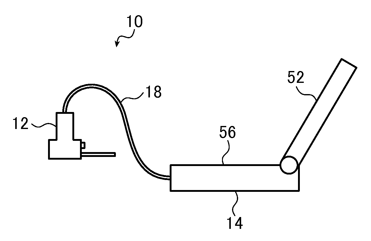
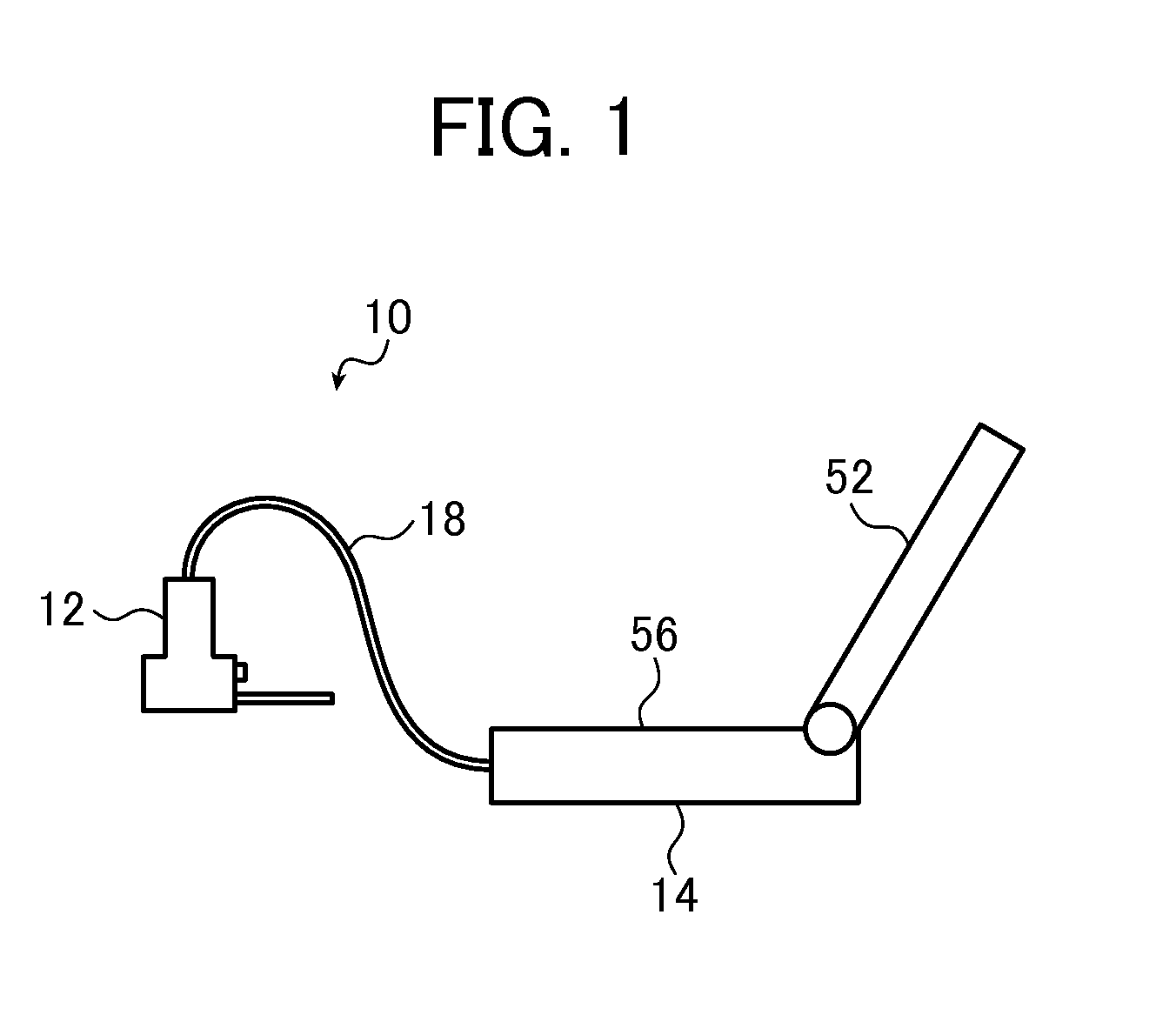
[0035]FIG. 1 is a conceptual diagram showing an embodiment of the ultrasound diagnostic apparatus of the invention.

[0036]The illustrated ultrasound diagnostic apparatus 10 is basically of a known type except that it is configured to calculate the insertion position from the target position inputted by reference to a generated ultrasound image and a preset insertion angle and to display the calculated insertion position.

[0037]The ultrasound diagnostic apparatus 10 of the invention includes an ultrasound probe 12, and a diagnostic apparatus body 14 which is connected to the ultrasound probe 12 via a communication cable 18.

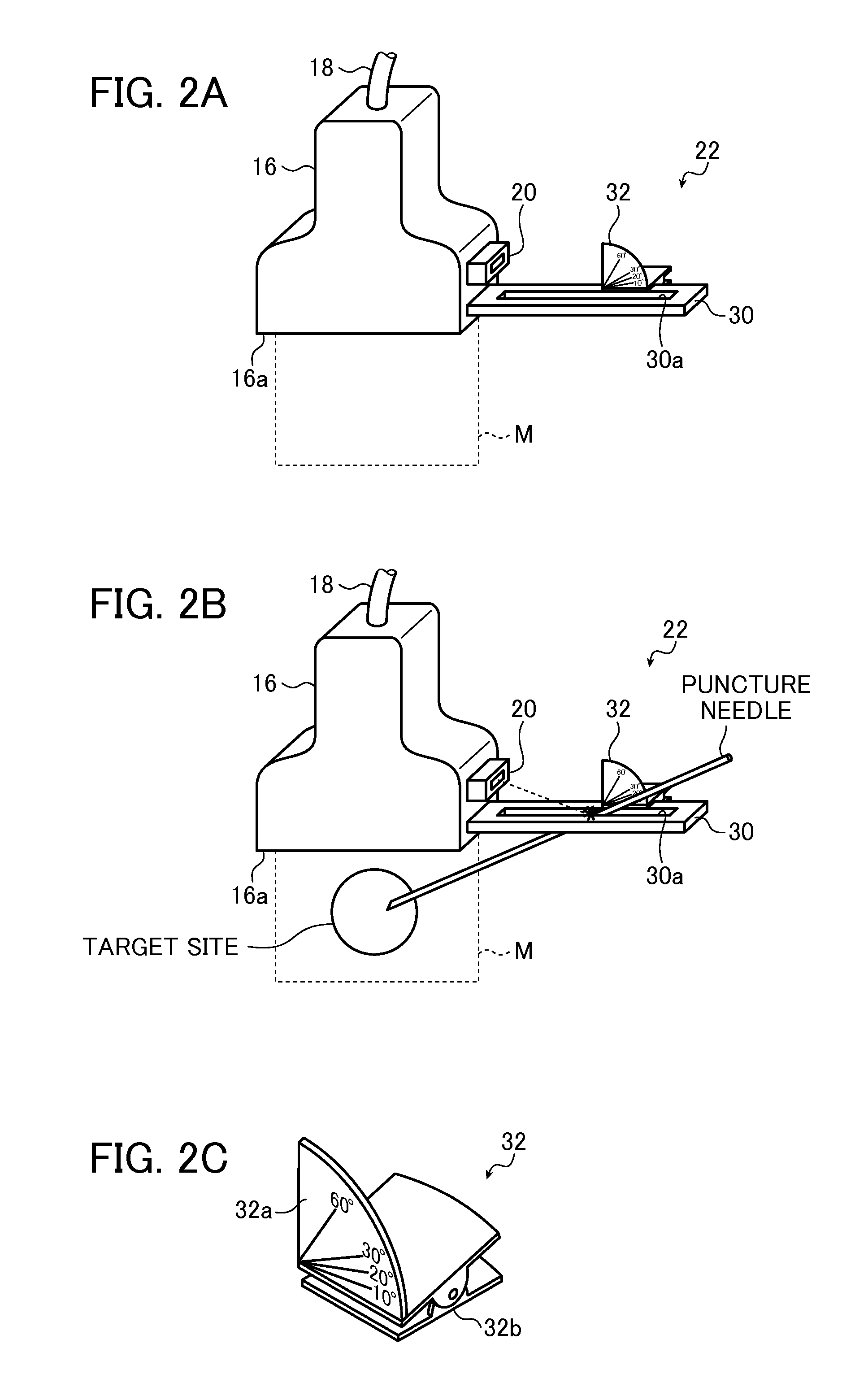
[0038]FIG. 2A is a schematic diagram showing the ultrasound probe 12. FIG. 2B is a schematic diagram showing the ultrasound probe 12, a puncture needle and a target site when paracentesis is performed.

[00...


PUM


Abstract

An ultrasound diagnostic apparatus includes an ultrasound probe, an image producer, a monitor, a position designating unit for designating a target position when paracentesis is performed, an insertion position calculating unit for calculating an insertion position from information on the target position designated by the position designating unit and a predetermined insertion angle and an insertion position display unit for displaying the insertion position calculated by the insertion position calculating unit. The ultrasound diagnostic apparatus ensures that a puncture needle inserted from a position away from an ultrasound probe to reduce the insertion angle so as to be imaged at a higher definition can also reach a target site.

Description

BACKGROUND OF THE INVENTION[0001]The present invention relates to an ultrasound diagnostic apparatus and more specifically to an ultrasound diagnostic apparatus that may be used in paracentesis.[0002]Heretofore, ultrasound diagnostic apparatuses that use ultrasound images have been put to use in the medical field. In general, this type of ultrasound diagnostic apparatus includes an ultrasound probe equipped with a built-in oscillator array and an apparatus body connected to the ultrasound probe. The ultrasound probe transmits ultrasonic waves toward a subject and receives ultrasonic echoes from the subject. The received signals are then electrically processed in the apparatus body to generate an ultrasound image.[0003]The ultrasound diagnostic apparatus is also used in paracentesis in which a doctor inserts a puncture device such as a puncture needle to a desired site and collects a tissue sample to make a cell / tissue diagnosis.[0004]In order-to ensure that the puncture needle reach...

Claims


Application Information

Patent Timeline
Patent Type & Authority Applications(United States)
IPC IPC(8): A61B8/14
CPCA61B8/0841A61B8/4427A61B8/4455A61B8/469A61B90/11A61B2090/067A61B2090/378
Inventor TASHIRO, RIKA
Owner FUJIFILM CORP
Why Eureka
Try Eureka