
Artificial disc

a technology for artificial discs and prostheses, applied in the field of prosthesis implants, can solve the problems of displacement or even dislocation of artificial discs, delay or failure of joint combination between upper and lower joints and adjacent vertebral sub-endplate bones, and improve mechanical environment , the effect of stable biological fixation

Active Publication Date: 2012-04-19
BEIJING NATON TECH GRP CO LTD
View PDF3 Cites 2 Cited by
  • Summary
  • Abstract
  • Description
  • Claims
  • Application Information

AI Technical Summary

Benefits of technology

[0005]To achieve the object above, the main idea of the invention is to restrict several relative movements between the upper joint and the lower joint of the artificial disc before the sclerotin grows into the combination surface by a temporary fixed connection, thereby enhancing the stableness between the upper and lower joints and the adjacent vertebral sub-endplate bones.
[0015]There are some drawbacks in the prior art: in the period before the sclerotin grows into the combination surface (contacting surface) of the artificial disc, the movement of the artificial disc causes that the upper and lower joints cannot combine stably with the adjacent vertebral sub-endplate bones, thereby delaying the combination process between the upper and lower joints and the adjacent vertebral sub-endplate bones. Aimed at the drawbacks above, the method of the invention is mainly to fix the position relation between the upper joint and the lower joint so as to form an “integral joint” in the above period. Although the “integral joint” is also movable to produce an unstableness at the combination surfaces of the upper and lower joints and the adjacent vertebral sub-endplate bones, compared with the conventional unstableness at the combination surfaces of the adjacent vertebral sub-endplate bones caused by the upper and lower joints both having freedom there between, the “integral joint” can resist movement and make the forming of the biological fixation more stable, so the unstableness of the combination surfaces between the upper joint and the adjacent vertebral sub-endplate bone and between the lower joint and the adjacent vertebral sub-endplate bone is greatly reduced. As a result, a better mechanical environment is provided for sclerotin to grow into the combination surface of the artificial disc, so as to form a stable biological fixation. After the sclerotin grew into the combination surface of the artificial disc, the fixed connection between the upper joint and the lower joint can be removed to make the artificialdisc recover the desired movement function.
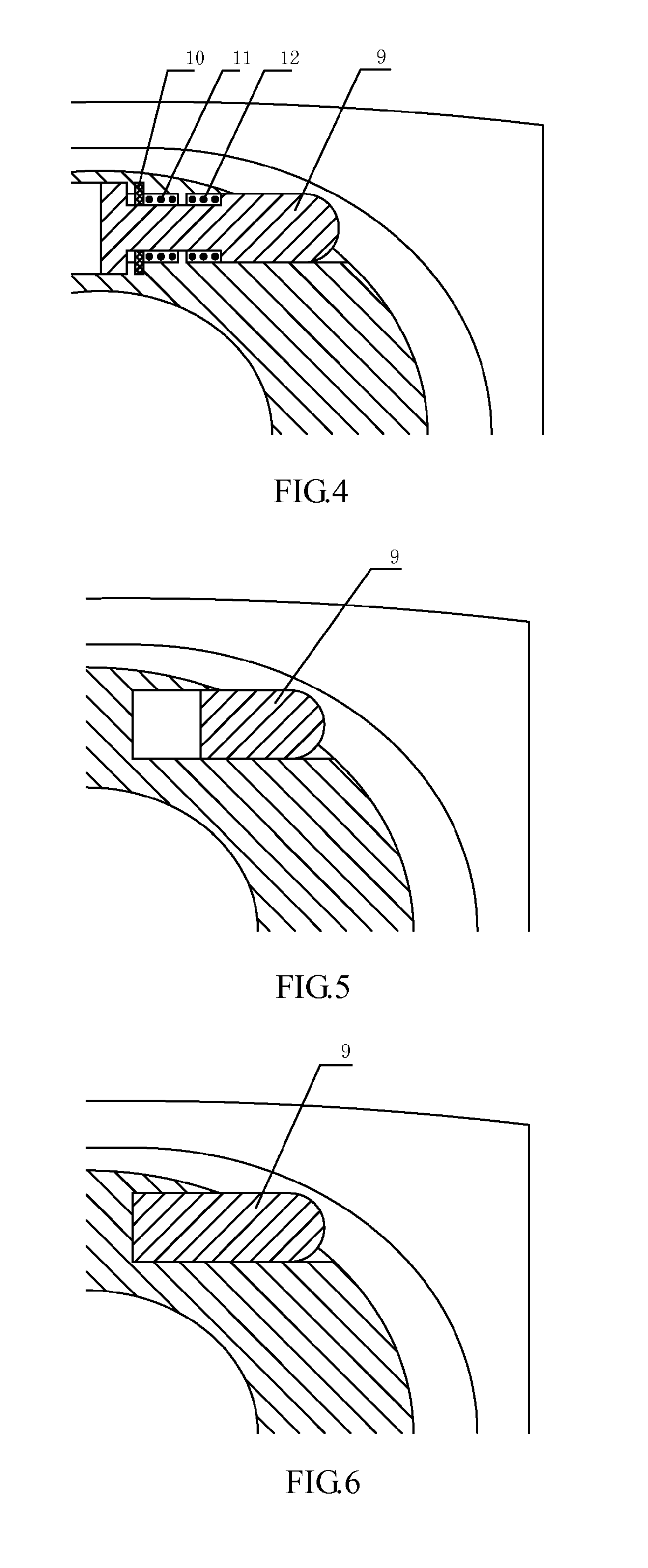
[0016]It can be learned from the above solutions, the artificial disc of the invention includes a temporary fixed connection structure for the upper and the lower joints base on the conventional artificial disc structure, thereby achieving the object of fixing the upper joint and the lower joint in the aforementioned growth stage of sclerotin. Moreover, in proper conditions (when the biological fixation is formed at the contacting surfaces between the upper and lower joints and the adjacent vertebral sub-endplate bones), the fixed connection structure can be removed to allow the upper joint and the lower joint to move relative to each other, and the artificial disc can recover its movement function.

Problems solved by technology

Before the sclerotin grows into the combination surface of the artificial disc, the combination surfaces of the upper and lower joints of the artificial disc and the adjacent vertebral sub-endplate bones are unstable due to a relative movement between the upper joint and the lower joint.
As a result, the combination between the upper and lower joints and the adjacent vertebral sub-endplate bones is delayed or fails at all.
Therefore, clinical reports about the artificial discs currently on the market often show occurrence of a displacement or even a dislocation of the artificial disc, as well as a related submergence of the artificial disc.

Method used


Image

  • Artificial disc
  • Artificial disc
  • Artificial disc

Examples


Embodiment Construction

[0026]A method for assembling an artificial disc will be described in detail according to embodiments of the invention hereinafter. However, it would be noted, the embodiments described here are intended only to illustrate, rather than to limit the scope of the invention.

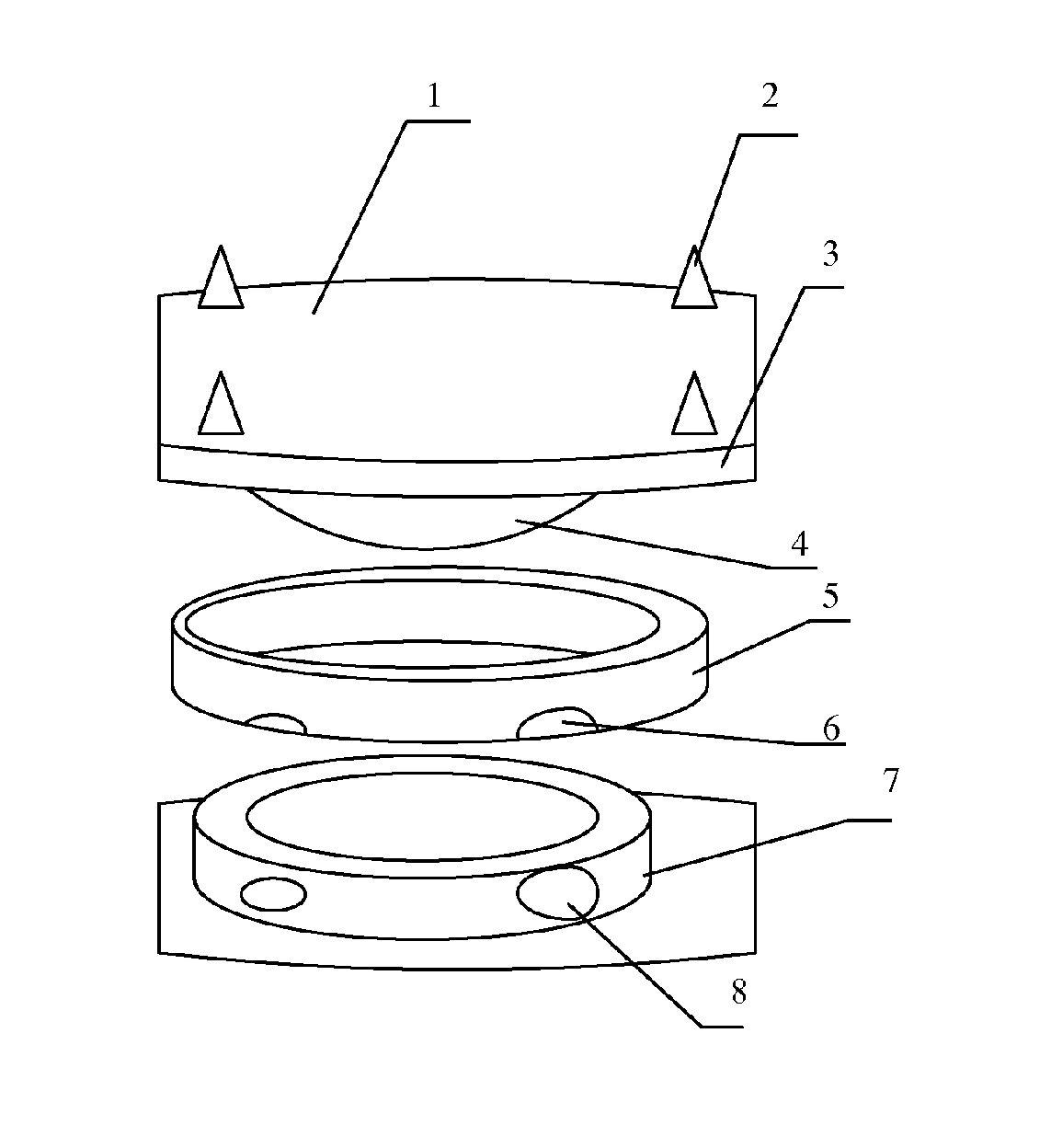
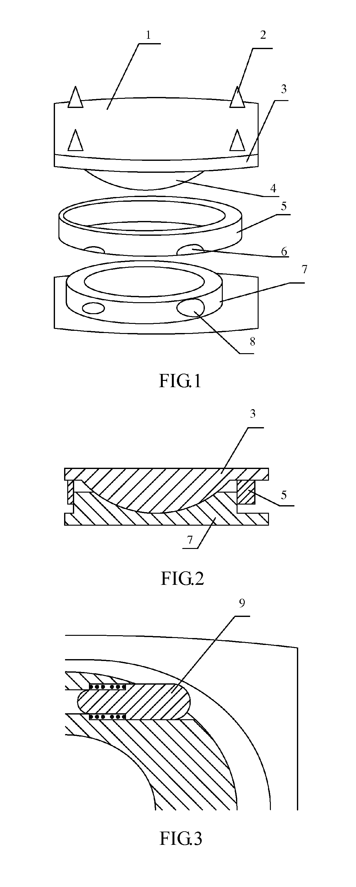
[0027]An upper joint and a lower joint of an artificial disc are assembled in accordance with a preset fixed position relation (referring to positions of the upper and lower joints shown in FIG. 1), that is, the upper and lower joints are fixed to adjacent vertebral sub-endplate bones, respectively, via spikes 2. The adjacent vertebral sub-endplate bones will apply pressure to the upper and lower joints downwardly and upwardly, which is very beneficial to make a stable fixation between the artificial disc and the adjacent vertebraes, especially before the sclerotin grew into the combination surface (namely, before a biological fixation is formed).

[0028]After disposing the upper and lower joints by the above step, a ...


PUM

PropertyMeasurementUnit
friction forceaaaaaaaaaa
movementaaaaaaaaaa
areaaaaaaaaaaa

Abstract

An artificial intervertebral disc includes an upper joint (3) and a lower joint (7) configured according to the corresponding upper and lower positions, and which includes a removable fixing structure which makes a permanent connection between the upper joint (3) and the lower joint (7).

Description

TECHNICAL FIELD[0001]The invention relates to the field of a prosthesis implants and, more particularly, to a intervertebral disc prosthesis.BACKGROUND ART[0002]An artificial disc replacement surgery is an effective way of treating degenerative disc diseases, and it gradually replaces the commonly-used spinal fusion surgery. The artificial disc replacement surgery has beneficial effects of restoring disc space height, decreasing stress concentration in adjacent segments, keeping a range of a joint motion (ROM) between adjacent vertebrals, preventing the degeneration of the zygapophyseal joint, and so on. The artificial disc replacement surgery uses a movable artificial disc as an implant to replace the natural disc and achieve moving function.[0003]A common artificial disc mainly includes an upper joint and a lower joint which are fixedly connected to their adjacent segments (adjacent vertebral sub-endplate bone / adjacent vertebral bone), respectively. A ball-socket structure is disp...

Claims


Application Information

Patent Timeline
Patent Type & Authority Applications(United States)
IPC IPC(8): A61F2/44B23P11/00
CPCA61F2/4425Y10T29/49826A61F2002/30649A61F2002/30841A61F2230/0065A61F2002/30062A61F2002/30079A61F2002/305A61F2002/30502A61F2002/30504A61F2002/30505A61F2002/30566A61F2002/30604A61F2002/30607A61F2002/30647A61F2002/30662A61F2002/302
Inventor CHENG, CHENG-KUNGCHAI, PENGZHAO, FUQIANGLIU, JIANXIANG
Owner BEIJING NATON TECH GRP CO LTD
Learn More