Electric vehicle and method for controlling the same
a technology for electric vehicles and vehicles, applied in vehicle position/course/altitude control, process and machine control, instruments, etc., can solve problems such as electric vehicles colliding with obstacles in moving directions, and achieve the effect of safe avoiding obstacles
- Summary
- Abstract
- Description
- Claims
- Application Information
AI Technical Summary
Benefits of technology
Problems solved by technology
Method used
Image
Examples
first embodiment
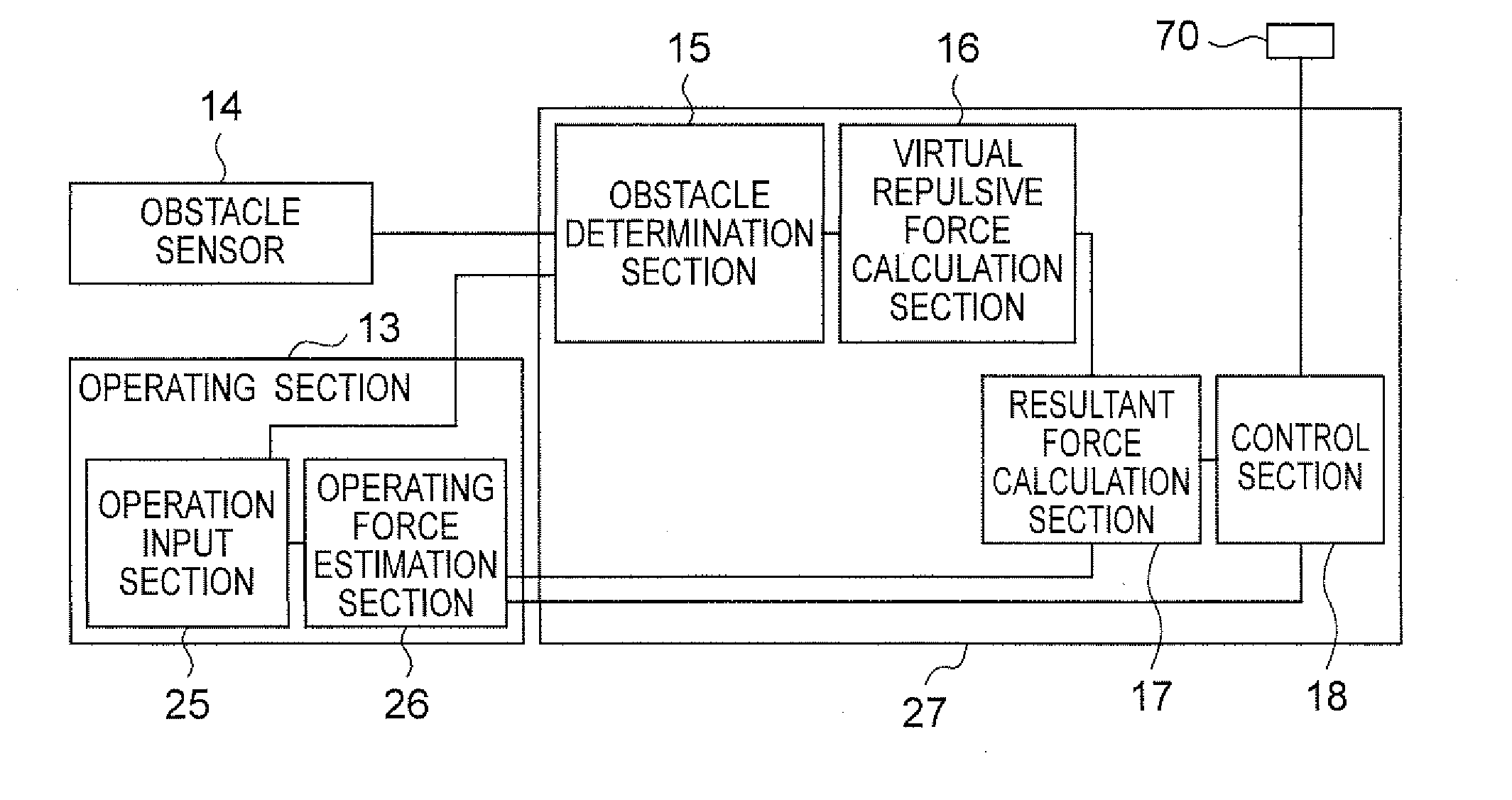
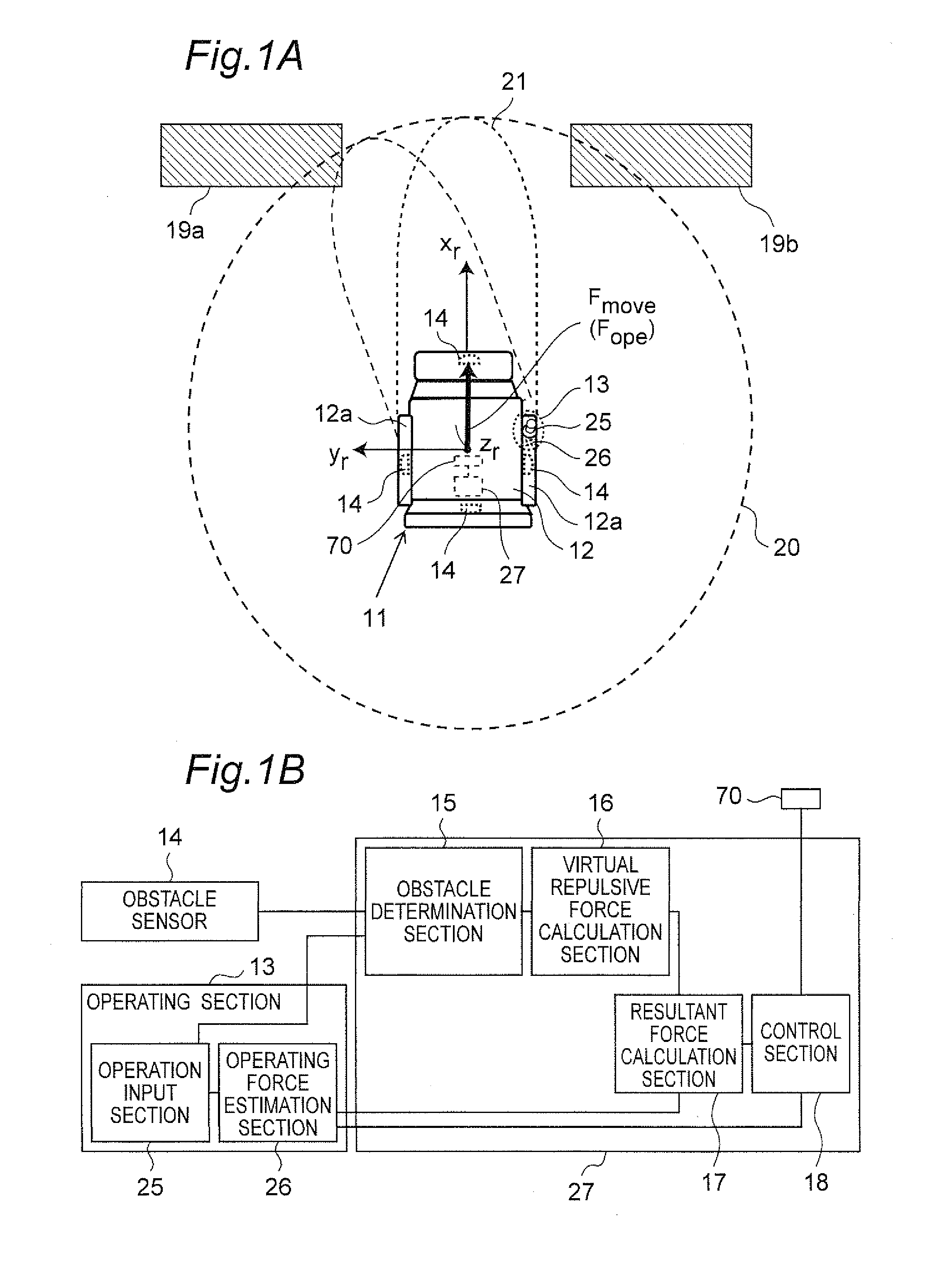
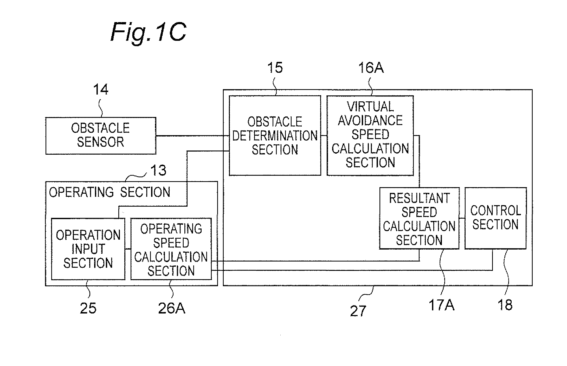
[0037]FIGS. 1A and 15 are views showing an electric wheelchair 11 in a planar manner as one example of an electric vehicle of a first embodiment of the present invention. FIG. 1A is a planar view showing the electric wheelchair 11 which is about to pass between an obstacle 19a and an obstacle 19b, and FIG. 1B is a block diagram of an operating section and a control section. FIG. 1C is a block diagram of an operating section and a control section of an electric wheelchair according to a variation of the first embodiment, and thus it will be described later. FIG. 2 is a perspective view of the electric wheelchair 11. In addition, for easy understanding, a vehicle coordinate system Er (coordinate system having three mutually orthogonal axes such as xr axis, yr axis, and zr axis) moving together with the motion of the electric wheelchair 11 is set in FIGS. 1A and 2. It is assumed that a plane composed of the xr axis and the yr axis is a horizontal plane parallel to a ground surface, and...
second embodiment
[0078]FIGS. 4A and 4B are views showing an electric wheelchair 31 according to a second embodiment of the present invention. FIG. 4A is a view showing the electric wheelchair 31 to which a dynamic obstacle 32 is coming close, and FIG. 42 is a block diagram of an operating section and a control section.
[0079]According to the electric wheelchair 31 of the second embodiment, when the dynamic obstacle 32 which moves by itself such as a person or a small animal comes close to the electric wheelchair 31, an auxiliary virtual repulsive force is generated by an auxiliary virtual repulsive force calculation section 34. Thus, based on this auxiliary virtual repulsive force, the electric wheelchair 31 is driven and controlled by the control section 18 through the resultant force calculation section 17 to automatically avoid the dynamic obstacle 32. That is, the electric wheelchair 31 according to the second embodiment has a dynamic obstacle search region 35 to detect the dynamic obstacle 32, i...
third embodiment
[0086]FIGS. 5A and 55 are views showing an electric wheelchair 41 according to a third embodiment of the present invention. FIG. 5A is a view showing the electric wheelchair 41 which is coming close to an obstacle, and FIG. 53 is a block diagram of an operating section and a control section.
[0087]The electric wheelchair 41 according to the third embodiment includes a control circuit section 47 instead of the control circuit section 27 of the electric wheelchair 11 according to the first embodiment. The control circuit section 47 further includes a collision determination section 42 and an auxiliary virtual repulsive force calculation section 43 in addition to the configuration of the control circuit section 27. The resultant force calculation section 17 calculates a resultant force composed of an operating force, a virtual repulsive force, and an auxiliary virtual repulsive force.
[0088]Thus, according to the electric wheelchair 41 of the third embodiment, in addition to the search r...
PUM
 Abstract
Description
Claims
Application Information
 - R&D
- Intellectual Property
- Life Sciences
- Materials
- Tech Scout
- Unparalleled Data Quality
- Higher Quality Content
- 60% Fewer Hallucinations
Browse by: Latest US Patents, China's latest patents, Technical Efficacy Thesaurus, Application Domain, Technology Topic, Popular Technical Reports.
© 2025 PatSnap. All rights reserved.Legal|Privacy policy|Modern Slavery Act Transparency Statement|Sitemap|About US| Contact US: help@patsnap.com


