

Acoustic apparatus and acoustic sensor apparatus including a fastener
a technology of acoustic sensor and acoustic noise, applied in the field of acoustic noise, can solve the problems of not providing continuous, detection and monitoring, and no known cost effective technology and product to detect loose electrical connections in electrical distribution systems
- Summary
- Abstract
- Description
- Claims
- Application Information
AI Technical Summary
Problems solved by technology
Method used
Image

Examples
example 1
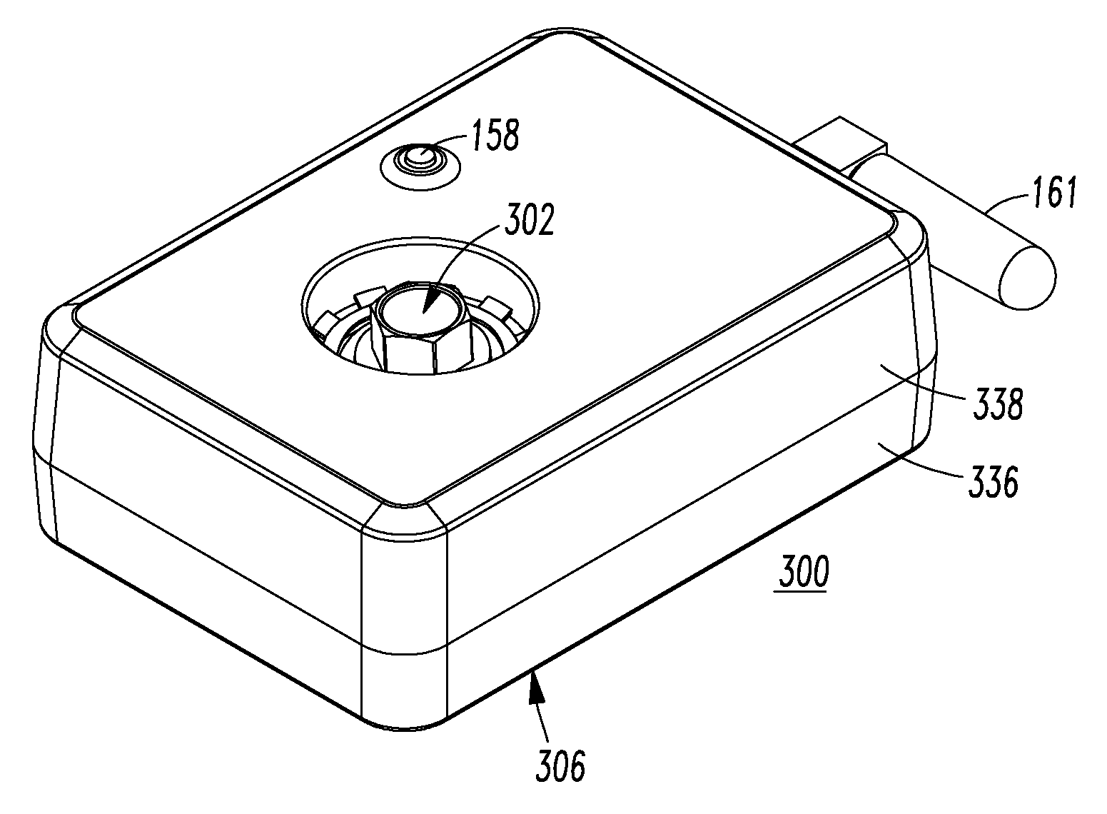
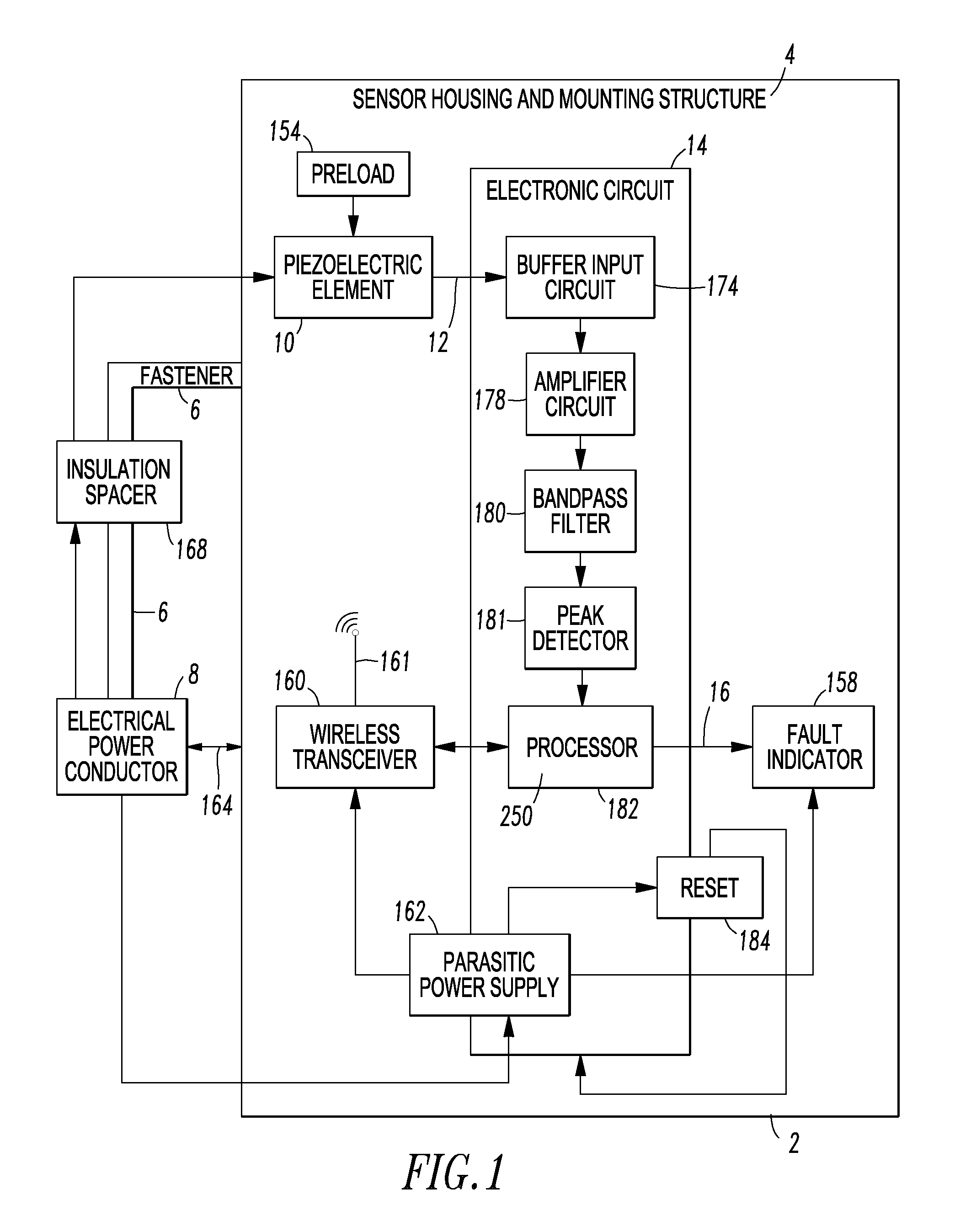
[0039]The example acoustic sensor apparatus 2 includes the example sensor housing and mounting structure 4, the fastener 6, the example piezoelectric element 10, an optional preload 154, the example electronic circuit 14 that outputs the electrical conductivity fault signal 16, a fault indicator 158, a communication device, such as a wired transceiver, a wired transmitter, a wireless transmitter, or a wireless transceiver 160 including an antenna 161, and a power supply 162.
[0040]The preload 154, which is not required, compresses the piezoelectric element 10 under pressure in its assembly. The “preload” means that the piezoelectric element 10 is compressed or under pressure in its assembly. The preload 154, which is applied to the example piezoelectric element 10, can be, for example and without limitation, a compression element such as a loaded compression spring.
[0041]The sensor housing and mounting structure 4 is suitably fastened, at 164, to an electrical power conductor 8 (e.g....
example 2
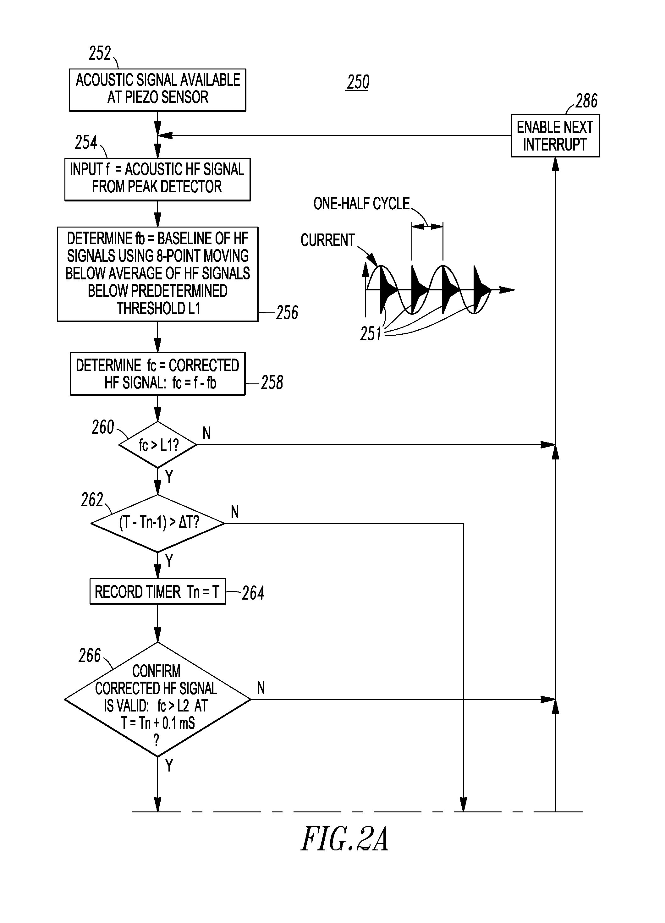
[0046]Referring to FIGS. 2A-2B, the routine 250 for the processor 182 of FIG. 1 is shown. The general operation of this routine 250 is to obtain output from the peak detector 181 of FIG. 1 and measure DELTA (step 268), the time difference between two adjacent signals from the peak detector 181. First, at 252, an acoustic signal is available at the piezoelectric element 10 and the peak acoustic signal therefrom is available at the peak detector 181. Next, at 254, the routine 250 inputs a signal, f, which is the acoustic high frequency (HF) signal from the peak detector 181.
[0047]Then, at 256, a value, fb, is determined, which is the baseline of the HF signals using, for example, an 8-point moving average of the HF signals below a predetermined threshold L1. Two L1 and L2 thresholds are employed by the routine 250 to confirm that acoustic wavelets 251 have the intended profile representative of an electrical conductivity fault. Non-limiting examples of L1 and L2 are 100 mV and 50 mV, ...
example 3
[0052]Referring to FIGS. 3-7, an acoustic sensor apparatus 300 includes a fastener, such as the example fastener structure 302, for an electrical power conductor, such as the example rectangular power bus bar 304 (shown in phantom line drawing in FIGS. 4 and 5). The example acoustic sensor apparatus 300 also includes a housing 306 for an acoustic sensor and / or an acoustic generator, such as a low cost piezoelectric element 308 (shown in FIG. 5) housed within the housing 306, and a printed circuit board (PCB) 310 (FIG. 5), which can include the example electronic circuit 14, fault indicator 158, wireless transceiver 160, parasitic power supply 162 and reset circuit 184 of FIG. 1. The housing 306 is fastened onto power bus bar 304 or another suitable power conductor (not shown) in an electrical system (not shown) by the fastener structure 302.
PUM
 Abstract
Description
Claims
Application Information