Cut out template

a template and template technology, applied in the field of cutting out templates, can solve the problems of incorrect alignment, hole size, location, etc., and achieve the effect of avoiding the possibility of affecting the installation process, and avoiding the installation of a templa

Inactive Publication Date: 2012-04-26
SP PROD
View PDF13 Cites 15 Cited by
  • Summary
  • Abstract
  • Description
  • Claims
  • Application Information

AI Technical Summary

Benefits of technology

[0007]In another form, the cavity may further include indentations indicating the centerline for both horizontal and vertical orientations to assist in the proper location of the template on the drywall or other surface.

Problems solved by technology

As such, the installation could be very time consuming, and if the worker is not skilled, mistakes may cause the hole to be sized, located, or aligned incorrectly.

Method used


Image

  • Cut out template
  • Cut out template

Examples


Embodiment Construction

[0012]While this device is susceptible of embodiments in many different forms, there is shown in the drawings and will herein be described in detail a preferred embodiment of the device with the understanding that the present disclosure is to be considered as an exemplification of the principles of the device and is not intended to limit the broad aspect of the device to embodiments illustrated.

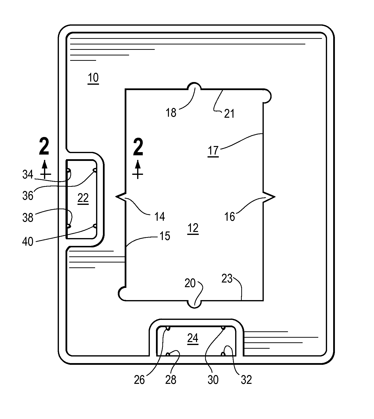
[0013]Referring to FIG. 1, there is illustrated a cut out template, generally designated by the numeral 10. The cut out template 10 has a cavity 12 of the approximate size and shape of an electrical box or device. Centering indentations 14 and 16 are located on each vertical edge 15 and 17 of the cavity 12, preferably in the center of each edge 15 and 17 of the cavity 12. Centering indentations 18 and 20 are also located on each horizontal edge 21 and 23 of the cavity 12, preferably in the center of each edge 21 and 23 of the cavity 12. In the embodiment pictured, the horizontal indentations ...


PUM


Abstract

A cut out template device is provided which enables fast installation of electrical boxes and devices by allowing for improved alignment and location. The cut out template includes a cavity having a size and shape approximating the size and shape of the electrical box and at least one leveler bubble for ensuring the template is level in either the horizontal or vertical direction.

Description

CROSS-REFERENCE TO RELATED APPLICATION[0001]This application claims the benefit of U.S. Provisional Patent Application No. 61 / 455,777, entitled “Cut Out Template,” filed Oct. 26, 2010.FIELD OF THE INVENTION[0002]The present device relates to a cut out template for alignment of electrical boxes and devices. Particularly, the present device relates to a template that allows for fast vertical and horizontal alignment of boxes and devices while minimizing damage to drywall.BACKGROUND[0003]In the typical construction or remodeling of a building structure, electrical wiring is accessed through electrical boxes such as outlet boxes, junction boxes, and electrical switches. These boxes, as well as other devices, typically provide access to electrical wiring through a hole in the wall, ceiling, or other surface. Often the boxes are installed at a uniform distance from the floor or at a uniform distance from some other structure. For aesthetic reasons, it is often desirable that the boxes be ...

Claims


Application Information

Patent Timeline
IPC IPC(8): G01B1/00G01C9/24
CPCG01B3/00G01B3/14H02G3/00H02G1/00G01C9/28H02G2200/30
Inventor EYERMANN, JOHNVRAME, PETER
Owner SP PROD
Why Eureka
Try Eureka