System for determining egr degradation

Active Publication Date: 2012-04-26
FORD GLOBAL TECH LLC
View PDF25 Cites 7 Cited by
  • Summary
  • Abstract
  • Description
  • Claims
  • Application Information

AI Technical Summary

Benefits of technology

[0002]EGR has long been provided to engines to control NOx emissions and reduce engine pumping work. EGR can lower engine pumping work by raising intake manifold pressure. EGR can lower NOx emissions by reducing peak in-cylinder combustion temperatures. More recently, EGR systems have started to cool EGR to further reduce in-cylinder combustion temperatures, thereby further reducing engine NOx emissions. However, cooled EGR is not necessary at all engine operating conditions and therefore some EGR systems provide both unconditioned and cooled EGR.
[0005]By providing separate and different models of EGR system behavior for each valve position, it is possible to better estimate EGR system behavior at least during some conditions. In one example, a model is provided to estimate EGR gas temperature downstream of an EGR cooler when a valve is commanded to a position where EGR gas is directed to the EGR cooler. A second model is provided to estimate EGR gas temperature downstream of the EGR cooler when the valve is commanded to a second position bypassing the EGR cooler. By providing separate models of different portions of the EGR system, it is possible to limit the effect that valve switching may have on individual models since the models can continue to estimate system parameters independent of valve position.
[0006]The present description may provide several advantages. In particular, the approach can improve model based parameter estimates since discontinuities that may be caused by switching a two state valve may not significantly influence the estimates provided by separate models. Further, the approach may be simpler to implement since all system dynamics do not have to be integrated into a single model to arrive at a desired model output. Further still, the present approach may simplify model calibration.

Problems solved by technology

However, cooled EGR is not necessary at all engine operating conditions and therefore some EGR systems provide both unconditioned and cooled EGR.
Although EGR systems can help to lower engine emissions and improve engine operation by providing both unconditioned and cooled EGR, such systems also provide challenges as to determining whether or not the system is operating as is desired.
For example, it may be difficult under some conditions to determine whether or not control valves are positioned as is desired to provide the requested cooled or unconditioned EGR.
However, adjusting a position of a two state cooler control valve can cause discontinuities in some modeled systems so that it may be difficult to assess whether or not operation of the EGR system is degraded.
If the discontinuities caused by switching a cooler control valve are not properly processed, false positive or false negative indications of EGR system degradation may result.

Method used


Image

  • System for determining egr degradation
  • System for determining egr degradation
  • System for determining egr degradation

Examples


Embodiment Construction

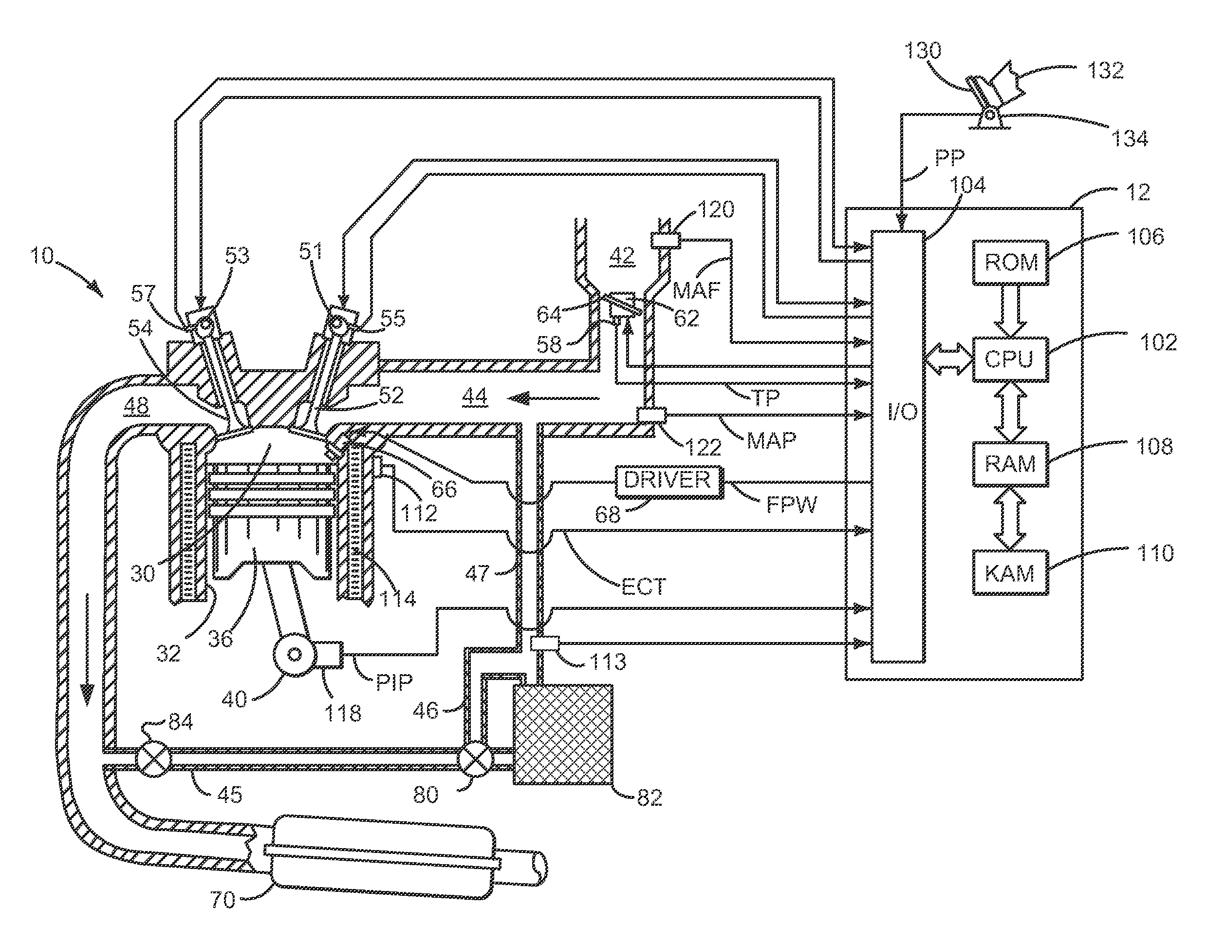
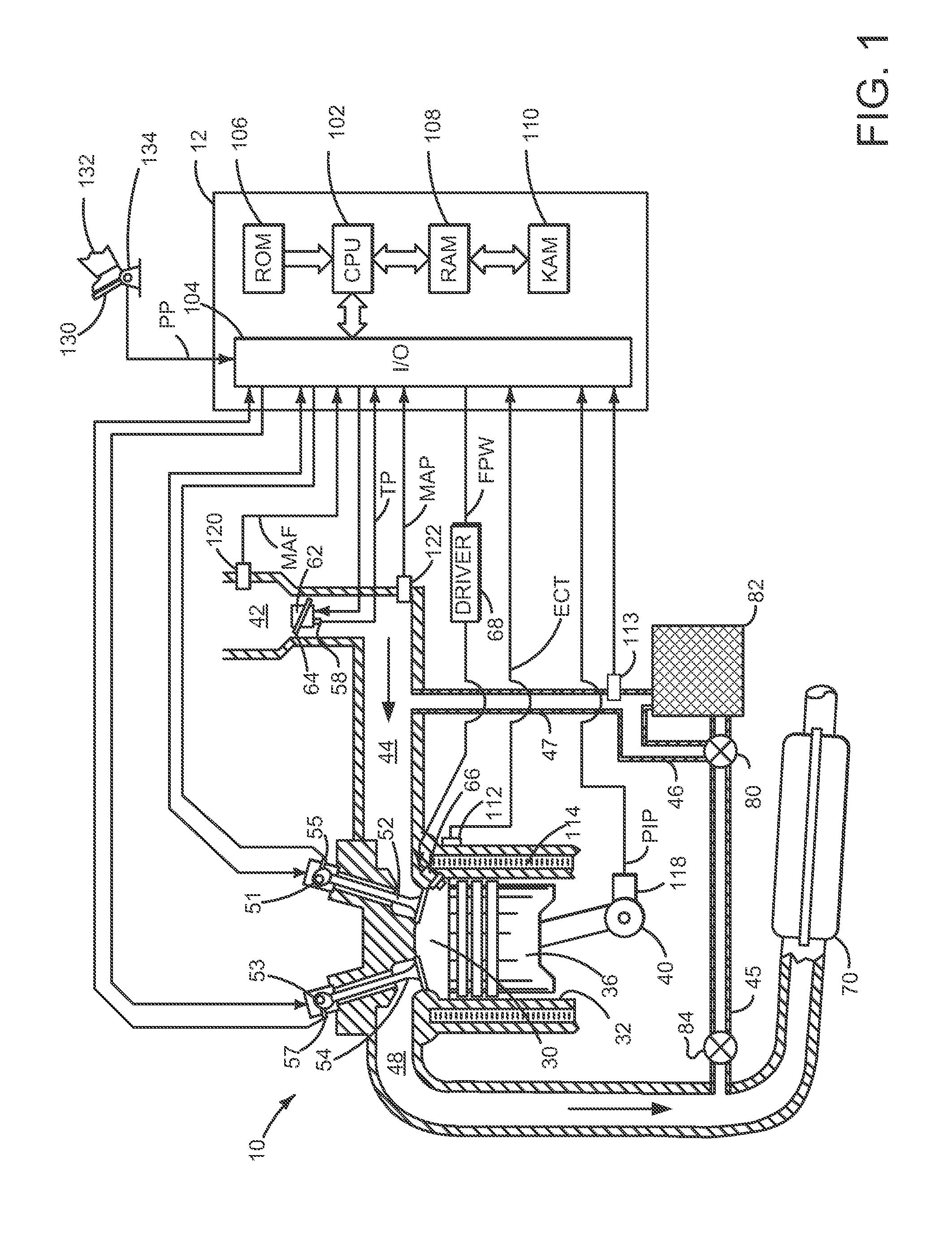
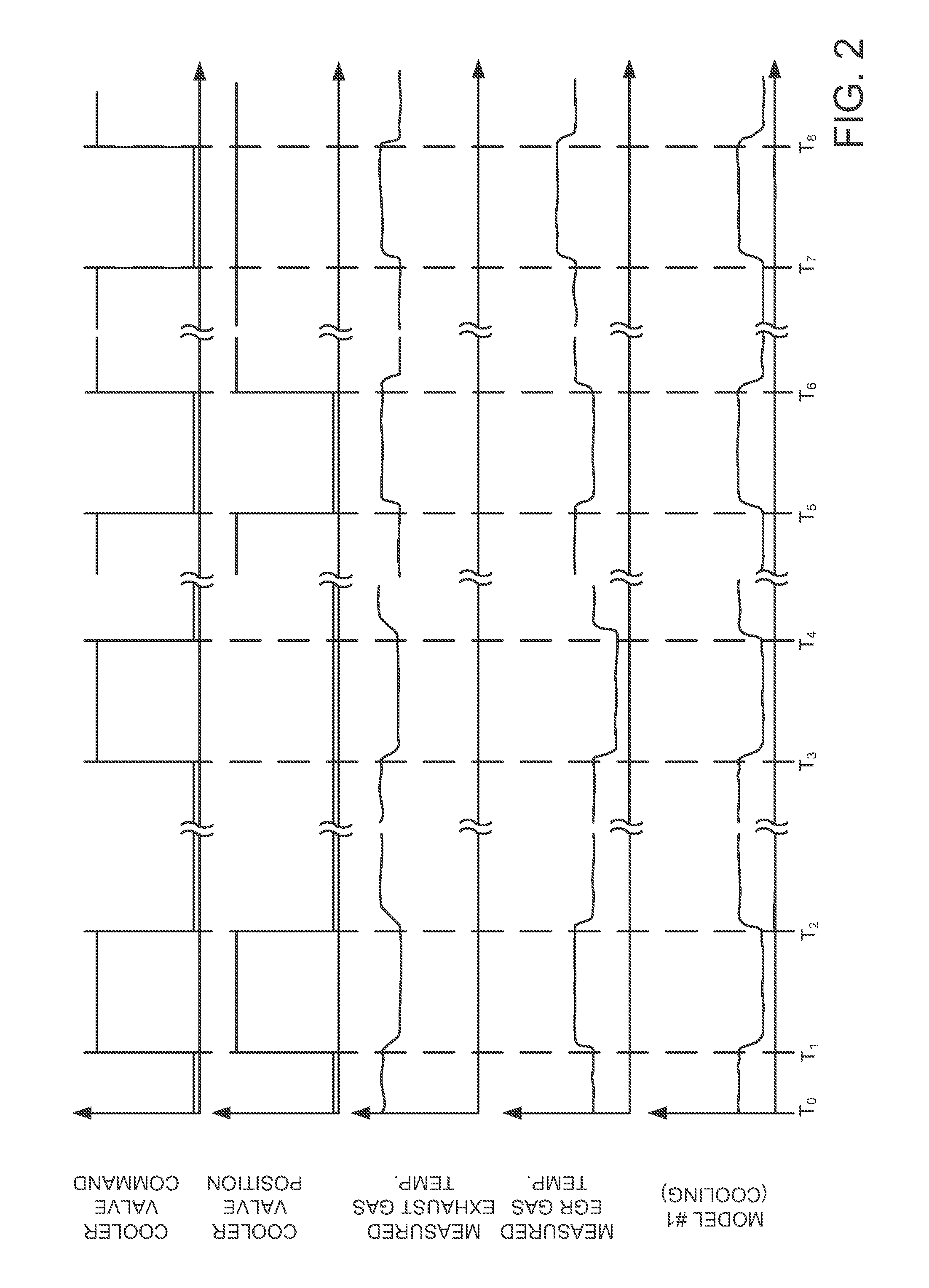
[0013]The present description is related to monitoring and determining degradation of an EGR system. In one example, the EGR system is adapted to a diesel engine as shown in FIG. 1. However, the present description may provide benefits for gasoline and alternative fuel engines as well. Accordingly, this disclosure is not limited to a particular type of engine or a particular EGR system configuration. FIGS. 2-3 show simulated signals of interest when an engine and EGR system are operated according to the method of FIG. 4.

[0014]Referring to FIG. 1, internal combustion engine 10, comprising a plurality of cylinders, one cylinder of which is shown in FIG. 1, is controlled by electronic engine controller 12. Engine 10 includes combustion chamber 30 and cylinder walls 32 with piston 36 positioned therein and connected to crankshaft 40. Combustion chamber 30 is shown communicating with intake manifold 44 and exhaust manifold 48 via respective intake valve 52 and exhaust valve 54. Each inta...


PUM


Abstract

A system for improving operation of an EGR system is presented. The system provides distinct models to estimate EGR temperature in response to a valve position. In one example, the system can judge EGR system operation when a state of a control valve is adjusted during driving conditions.

Description

FIELD [0001]The present description relates to a method and system for improving operation and diagnosis of an exhaust gas recirculation (EGR) system. The approach may be particularly useful for engines that have cooled EGR.BACKGROUND AND SUMMARY [0002]EGR has long been provided to engines to control NOx emissions and reduce engine pumping work. EGR can lower engine pumping work by raising intake manifold pressure. EGR can lower NOx emissions by reducing peak in-cylinder combustion temperatures. More recently, EGR systems have started to cool EGR to further reduce in-cylinder combustion temperatures, thereby further reducing engine NOx emissions. However, cooled EGR is not necessary at all engine operating conditions and therefore some EGR systems provide both unconditioned and cooled EGR.[0003]Although EGR systems can help to lower engine emissions and improve engine operation by providing both unconditioned and cooled EGR, such systems also provide challenges as to determining whe...

Claims


Application Information

Patent Timeline
IPC IPC(8): F02B33/44G01M15/10
CPCF02D41/0072F02D41/1446F02D41/221F02D2041/0067F02D2041/007F02M25/0727F02M25/0728F02M25/0731F02M25/0738F02M25/0754Y02T10/47F02M25/0702F02M26/23F02M26/25F02M26/28F02M26/33F02M26/47F02M26/49Y02T10/40
Inventor FARMER, MARY CATHERINE
Owner FORD GLOBAL TECH LLC
Why Eureka
Try Eureka