Detection device, electronic apparatus, and robot

a detection device and electronic technology, applied in the direction of instruments, manufacturing tools, force/torque/work measurement apparatus, etc., can solve the problems of inability to appropriately measure the intensity of external pressure in the horizontal direction, inability to detect detection errors, and inability to appropriately detect external pressure applied to the detection device. achieve the effect of high accuracy

Active Publication Date: 2012-04-26
SEIKO EPSON CORP
View PDF4 Cites 15 Cited by
  • Summary
  • Abstract
  • Description
  • Claims
  • Application Information

AI Technical Summary

Benefits of technology

[0031]According to the robot of the aspect of the invention, since the robot includes the above-described detection devices, it is possible to provide a robot capable of detecting the direction and the intensity of the external pressure with high accuracy.

Problems solved by technology

That is, a detection error occurs such as detecting the direction opposite to the direction in which the external pressure is applied.
Therefore, the external pressure which is applied to the detection device cannot be appropriately detected.
In a state where the deviation between the center of gravity of the elastic body and the reference position of the pressure-sensitive element remains, there is a problem in that the intensity of the external pressure in the horizontal direction cannot be appropriately measured.
Thus, there are problems in that the bonded surface between the columnar body and the pressure-receiving sheet is easily collapsed and the durability is deteriorated.
In the approximately hemispherical elastic protrusion, since a tip portion thereof faces the second substrate and is disposed in the first substrate, even in a state where the sliding force is applied to the elastic protrusion, it is difficult to generate the deviation of the horizontal position of the contact surface of the elastic protrusion, which comes into contact with the first substrate.

Method used


Image

  • Detection device, electronic apparatus, and robot
  • Detection device, electronic apparatus, and robot
  • Detection device, electronic apparatus, and robot

Examples


first embodiment

Detection Device

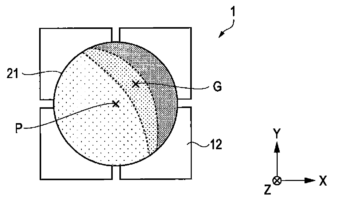
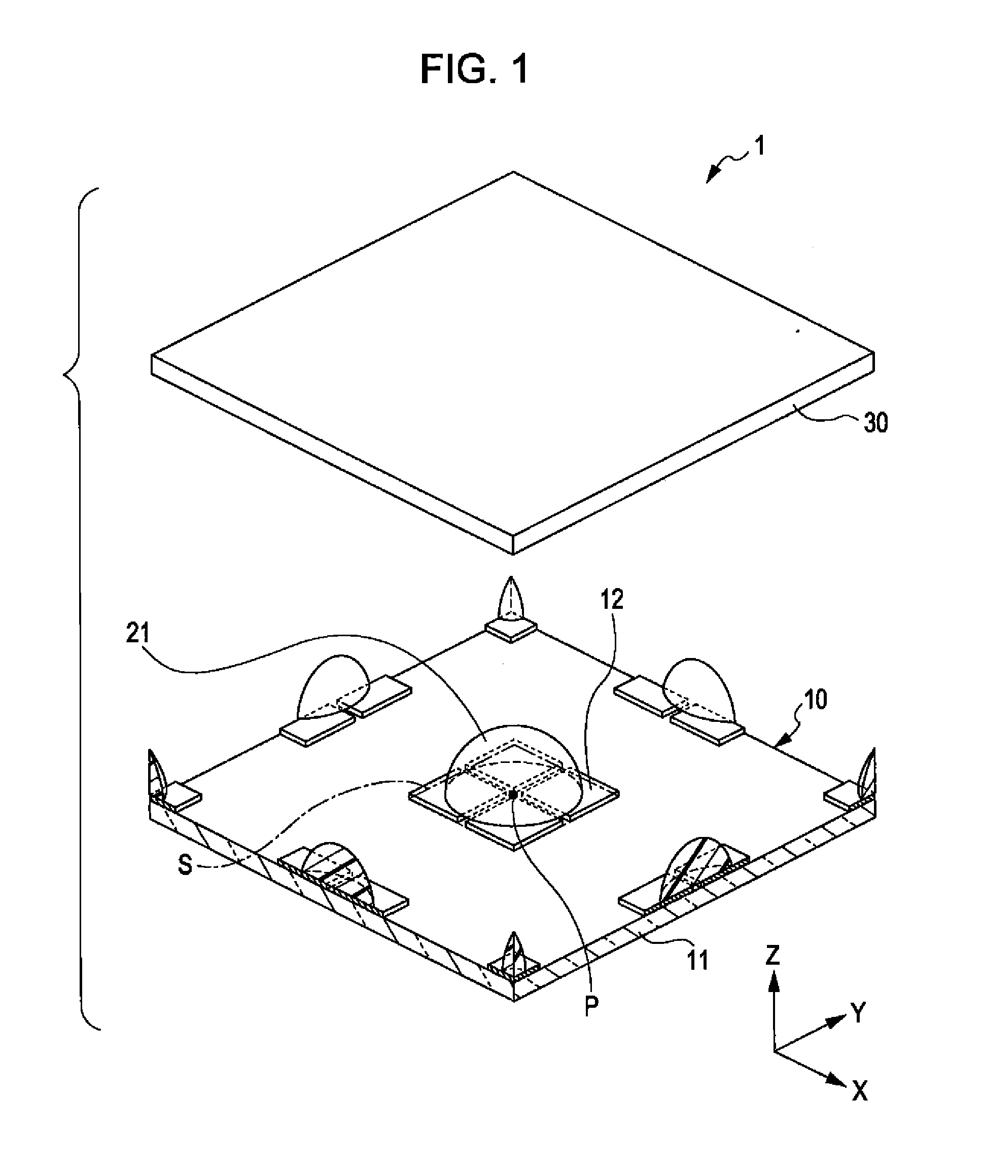
[0052]FIG. 1 is an exploded perspective view showing a schematic configuration of a detection device according to a first embodiment of the invention. In FIG. 1, a reference number P indicates a reference point, and a reference number S indicates a unit detection region that is detected by a plurality of pressure sensors 12 which are disposed corresponding to one elastic protrusion 21.

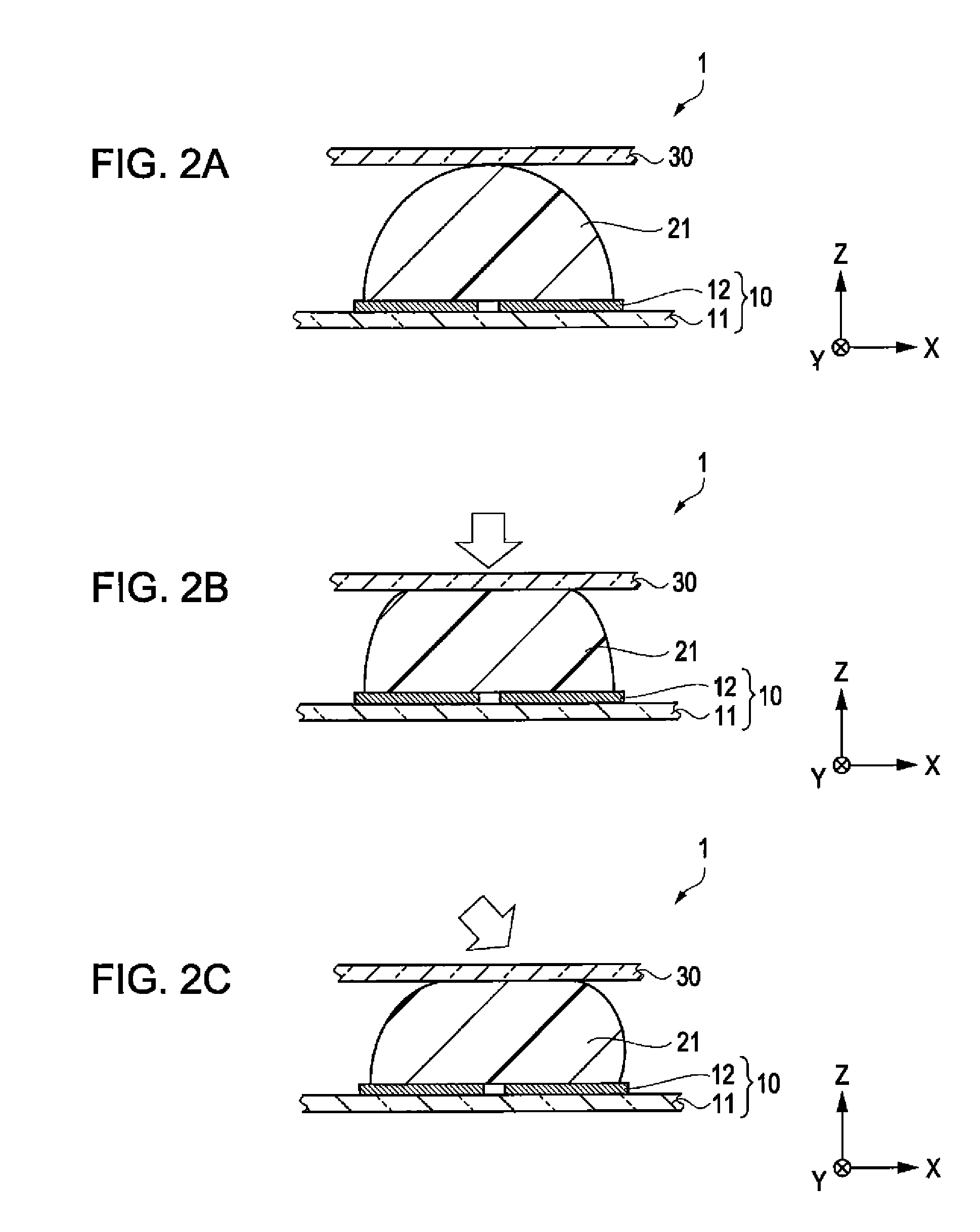
[0053]A detection device 1 is a pressure sensor type touch pad that detects the direction and the intensity of the external pressure which is applied to the reference point. For example, the detection device 1 is a pointing device which is used instead of a mouse in an electronic apparatus such as a notebook computer. In addition, the “reference point P” is a point in which a center of the elastic protrusion 21 is disposed when a sliding force is not applied.

[0054]As shown in FIG. 1, the detection device 1 includes: the first substrate 10 that includes pressure sensors 12 which are disp...

second embodiment

[0098]FIG. 8 is an exploded perspective view which corresponds to FIG. 1 and shows a schematic configuration of a detection device according to a second embodiment of the invention. In FIG. 8, the same reference numbers are denoted with respect to the same components as FIG. 1, and the detailed description thereof is omitted. In FIG. 8, the reference number P indicates the reference point, and the reference number S indicates the unit detection region in which the plurality of pressure sensors 112, which is disposed corresponding to one elastic protrusion 21, detects.

[0099]The detection device 2 of the second embodiment is different to the detection device 1 described in the first embodiment in that the plurality of pressure sensors 112 is disposed in at least 4 rows in length×4 columns in width in two directions which are perpendicular to each other. In addition, in FIG. 8, for convenience, the plurality of pressure sensors 112 is disposed in 4 rows in length×4 columns in width per...

third embodiment

[0117]FIG. 12 is a cross-sectional view corresponding to FIG. 9A showing a schematic configuration of a detection device according to a third embodiment of the invention. In addition, only one elastic protrusion 21 is shown in FIG. 9A, but two adjacent elastic protrusions 22 are shown in FIG. 12. The detection device3 of the third embodiment is different from the detection device 2 of the above-described second embodiment in that the elastic protrusion 22 is disposed making contact with the first substrate main body 111. In FIG. 12, the same reference numbers are denoted with respect to the same components as FIG. 9, and the detailed description thereof is omitted.

[0118]According to the third embodiment, since the elastic protrusion 22 makes contact with the first substrate main body 111 and is disposed, even in the state where the sliding force is applied to the second substrate 30, the horizontal position of the contact surface of the elastic protrusion 22 which comes into contact...


PUM

PropertyMeasurementUnit
length×56aaaaaaaaaa
length×2aaaaaaaaaa
diameteraaaaaaaaaa

Abstract

A first substrate that includes pressure sensors which are disposed in plural around a reference point; an approximately hemispherical elastic protrusion that is positioned so that the center of the elastic protrusion is approximately disposed in a position which is overlapped with the reference point, and is elastically deformed by an external force; and a second substrate that is separated from the elastic protrusion and installed on a side which is opposite to the first substrate are provided. When the external force is applied, a predetermined calculation is performed by using a pressure value which is detected through each pressure sensor, and the direction and the intensity of the applied external force are obtained.

Description

[0001]This application claims priority to Japan Patent Application No. 2010-237153 filed Oct. 22, 2010, the entire disclosures of which are hereby incorporated by reference in their entireties.BACKGROUND[0002]1. Technical Field[0003]The present invention relates to a detection device, an electronic apparatus, and a robot.[0004]2. Related Art[0005]As a device that detects an external force, detection devices as described in JP-A-2008-164557, JP-A-2007-187502, and Japanese patent No. 4364146 are known. It has been considered to apply the detection devices to a tactile sensor or the like of a touch panel or a robot.[0006]In the detection device of JP-A-2008-164557, a plurality of contacts, which includes a bulged portion, is installed on a surface of a pressure-sensitive element. In addition, the pressure distribution and the pressure in a horizontal direction are detected from a load applied to each contact or a movement of each contact. However, in the detection device of JP-A-2008-1...

Claims


Application Information

Patent Timeline
Patent Type & Authority Applications(United States)
IPC IPC(8): G01L1/04
CPCB25J13/083G01L1/02G01L1/04G01L5/009G06F3/0414G01L1/205B25J19/02G01L1/00G01L5/00
Inventor AMANO, TAKAHIROIKEBE, TOMO
Owner SEIKO EPSON CORP
Why Eureka
Try Eureka