Heat sink

Inactive Publication Date: 2012-04-26
FURUKAWA ELECTRIC CO LTD
View PDF8 Cites 7 Cited by
  • Summary
  • Abstract
  • Description
  • Claims
  • Application Information

AI Technical Summary

Benefits of technology

[0023]According to the heat sink of the present invention, two kinds of thin plate fins having different heights are used in adjacent to each other, low thin plate fins are provided at a main part and high thin plate fins are arranged at ends, and all the thin plate fins are thermally connected to the heat pipes. Besides, as a part of a heat pipe is inserted into t

Problems solved by technology

However, enhancement in performance of CPU, MPU and the like mounted on a notebook-size personal computer, a laptop or desktop computer causes an associated increase in generated heat.
Cooling of heat generating components such as high-performance CPU and MPU has been always weighted heavily as an important technical issue.
Al

Method used


Image

  • Heat sink
  • Heat sink
  • Heat sink

Examples


Embodiment Construction

[0036]With reference to the drawings, a heat sink of the present invention will be described below.

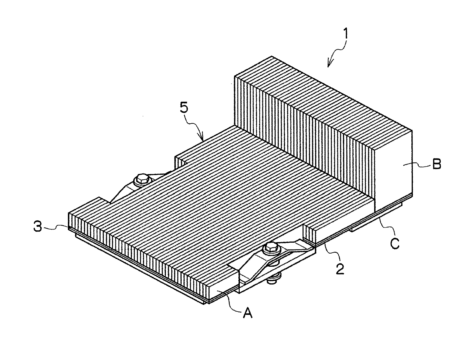
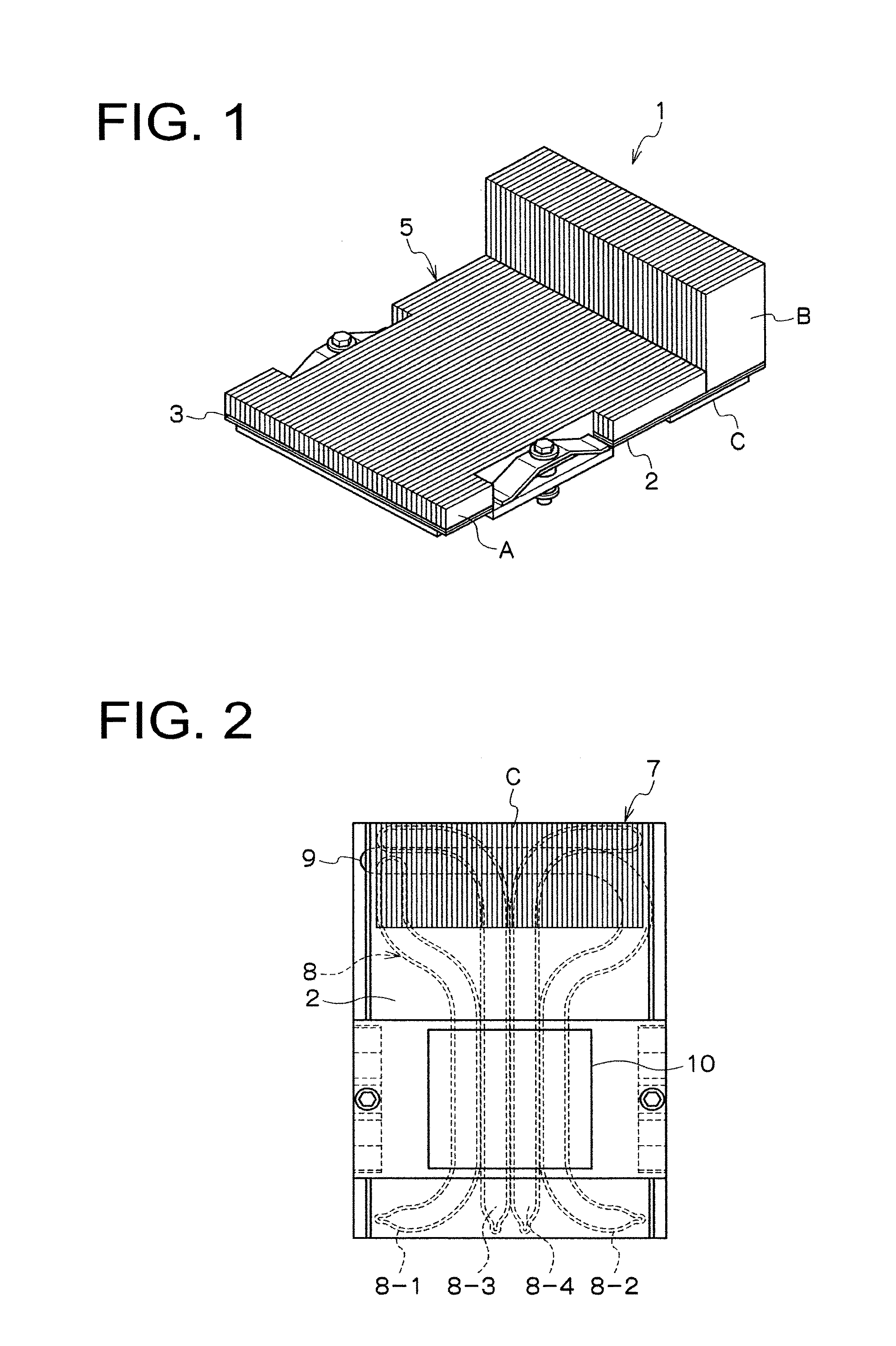
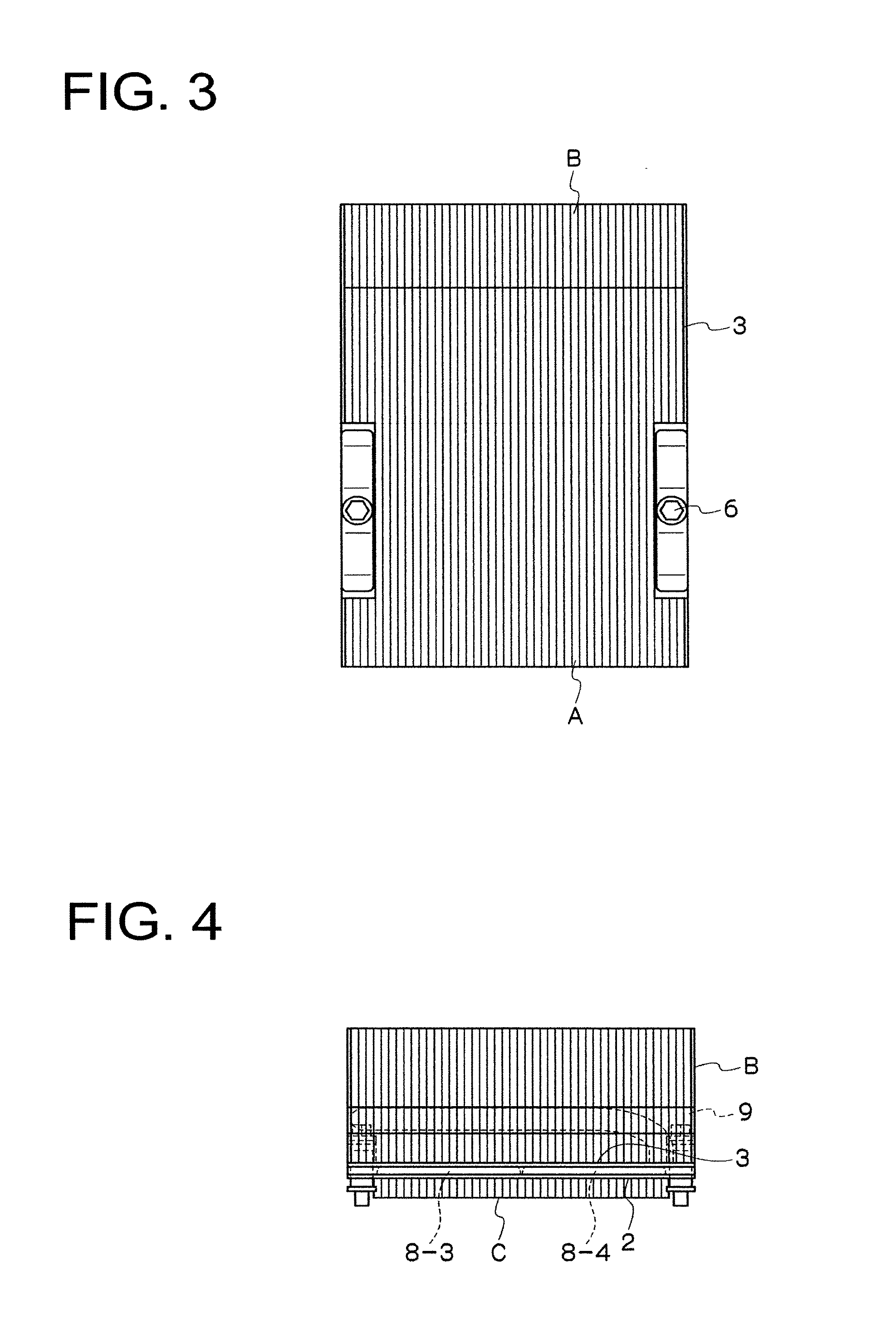
[0037]The heat sink according to an embodiment of the present invention has a base plate which has one surface thermally connected to a heat generating component and which has thermally connected thereto a first heat dissipating fin section composed of a thin plate fin; an upper plate which has a second heat dissipating fin section thermally connected to one surface, the second heat dissipating fin section being composed of two kinds of thin plate fins having different heights; and a plurality of heat pipes which are disposed between the other surface of the base plate and the other surface of the upper plate by being thermally connected to the surfaces and which include a heat pipe that has at least a part thereof inserted into a part of the second heat dissipating fin section. The first heat dissipating fin section is preferably connected to the base plate, but may not be connected t...


PUM


Abstract

Provided is a heat sink capable of improving heat dissipating characteristics and saving space with a reduced fin size. The heat sink is provided with: a base plate which has one surface thermally connected to a heat generating component and which has thermally connected thereto a first heat dissipating fin section composed of a thin plate fin; an upper plate which has a second heat dissipating fin section thermally connected on one surface, the second heat dissipating fin section being composed of two kinds of thin plate fins having different heights; and a plurality of heat pipes which are disposed between the other surface of the base plate and the other surface of the upper plate by being thermally connected to the surfaces and which include a heat pipe that has at least a part thereof inserted into a part of the second heat dissipating fin section.

Description

TECHNICAL FIELD[0001]The present invention relates to a heat sink used to cool a component to be cooled (hereinafter, referred to as “cooled component”), for example, a heat generating component such as CPU or MPU in an electronic device.BACKGROUND ART[0002]Recently, various electric and electronic devices such as a personal computer have been enhanced in performance and downsized. However, enhancement in performance of CPU, MPU and the like mounted on a notebook-size personal computer, a laptop or desktop computer causes an associated increase in generated heat. On the other hand, demands for downsizing of the electric and electronic devices and saving space inside the electric and electronic devices have grown more.[0003]Cooling of heat generating components such as high-performance CPU and MPU has been always weighted heavily as an important technical issue. Also for electric and electronic devices other than computers, cooling of high-performance heat generating components and h...

Claims


Application Information

Patent Timeline
IPC IPC(8): F28D15/04
CPCH01L23/3672H01L23/427H01L2924/0002H01L2924/00F28D15/0275
Inventor FURUMOTO, SHINICHIITO, SHINICHIKAWABATA, KENYA
Owner FURUKAWA ELECTRIC CO LTD
Why Eureka
Try Eureka