Suction cup apparatus for attachment to porous and nonporous surfaces

Inactive Publication Date: 2012-04-26
ZOYA
View PDF16 Cites 7 Cited by
  • Summary
  • Abstract
  • Description
  • Claims
  • Application Information

AI Technical Summary

Benefits of technology

[0013]The relatively high level of hardness of the first elastomer is needed to prevent tearing and to provide sufficient force to form a partial vacuum between the concave surface and a surface to which the suction cup is attached, such as a wall. The relatively low level of hardness of the second elastomer is needed to provide for reliable attachment to a porous surface, such as a gypsum wallboard, with the elastomeric material moving into pores within the porous surface.
[0014]According to another aspect of the invention, apparatus for attachment to a wall, comprising a housing and a suction cup as described above, is provided, with the suction cup being atta

Problems solved by technology

This leakage of air reduces the level of partial vacuum within this space, so that the device f

Method used


Image

  • Suction cup apparatus for attachment to porous and nonporous surfaces
  • Suction cup apparatus for attachment to porous and nonporous surfaces
  • Suction cup apparatus for attachment to porous and nonporous surfaces

Examples


first embodiment

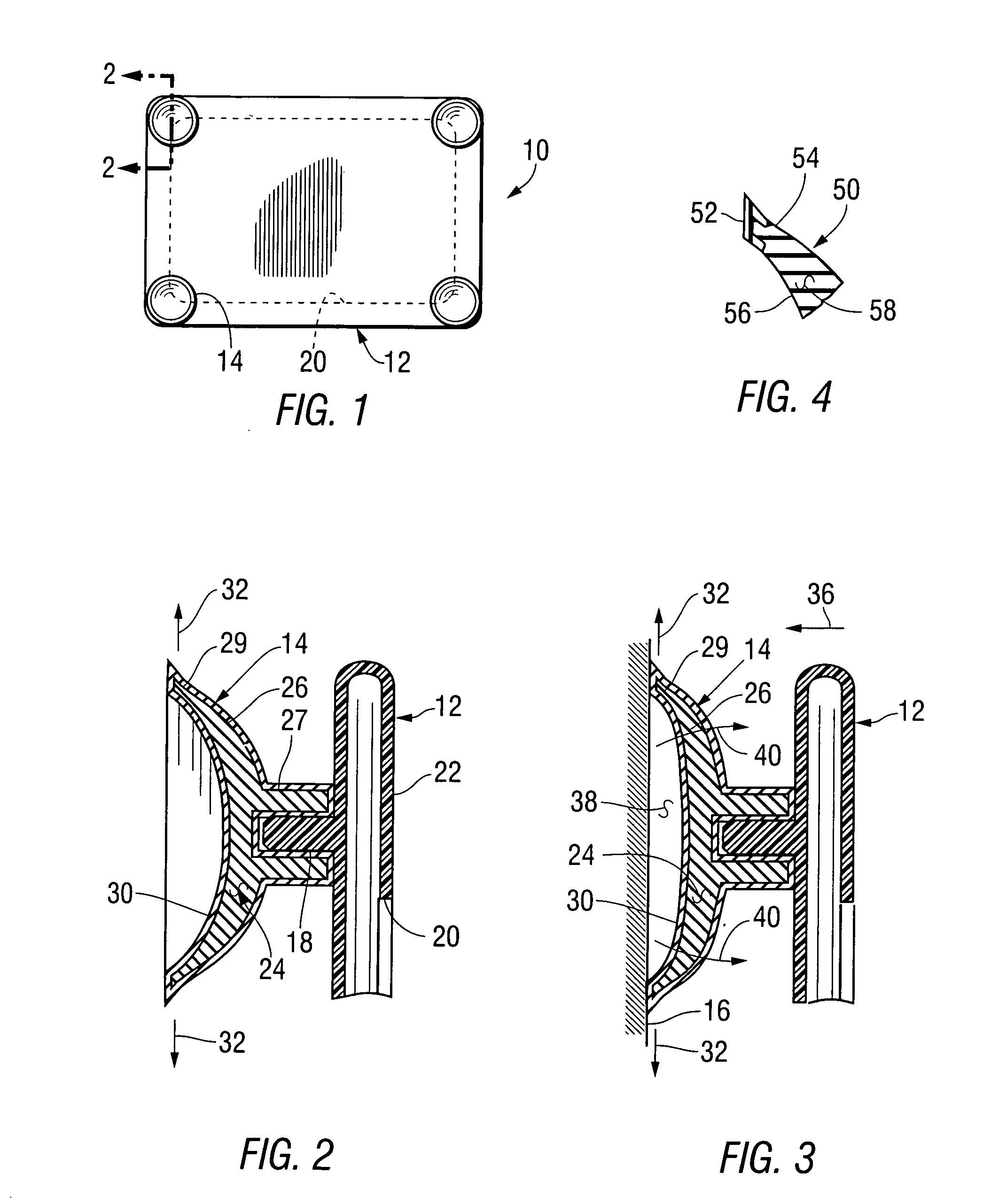
[0036]FIG. 1 is a rear elevation of an device 10 for attachment to a wall built in accordance with the invention to include a housing 12 and four suction cups 14 for attaching the device 10 to a wall surface 16 (shown in FIG. 3.)

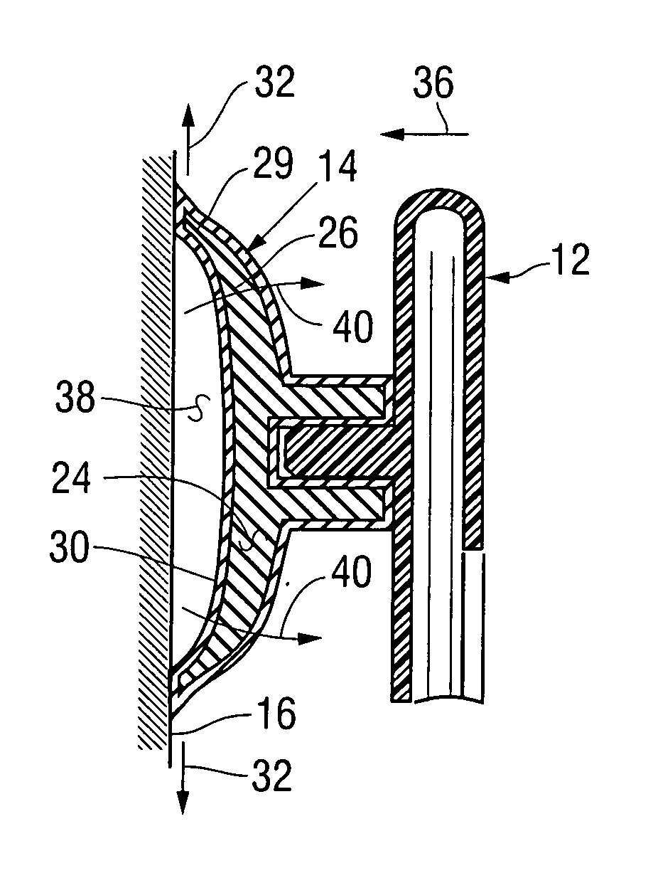
[0037]FIG. 2 is a fragmentary cross-sectional side elevation of the device 10, taken as indicated by section lines 2-2 in FIG. 1 to show one of the suction cups 14, which is attached to the housing 12 by being pushed onto a pin 18 forming part of the housing 12. For example, the housing 12 is formed as a picture holder having an opening 20 in a front surface 22. In accordance with the invention, the suction cup 14 comprises a core 24, composed of a relatively tough elastomeric material, and an outer layer 26, composed of a relatively soft elastomeric material. The core 24 forms a central portion 27, a disk-shaped portion 28, and an annular peripheral portion 29. The disk-shaped portion 28 has an outward-facing concave surface 30 extending radially, in the di...

second embodiment

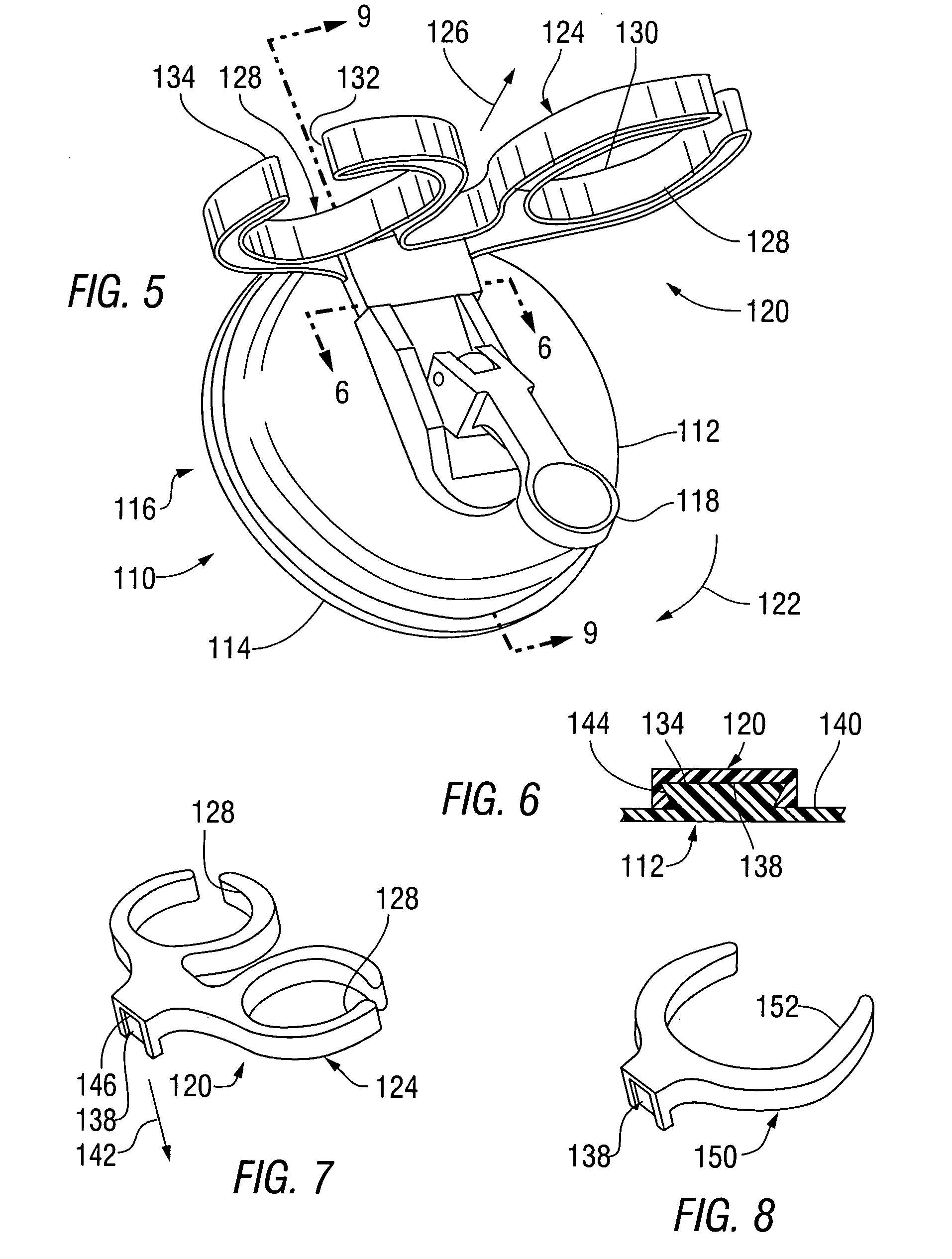
[0043]FIG. 5 is a perspective view of a device 110, built in accordance with the invention, shown as seen from below, in front, and from the left. The device 110 includes a housing 112, a suction cup 114 extending along a rear side 116 of the housing, a pivoted actuator 118, and a bracket 120. When the suction cup 114 is held against a wall surface (not shown), the pivoted actuator 118 is moved in a first direction, indicated by arrow 122, to cause the suction cup 114 to be held against the wall surface, and opposite the first direction to cause the suction cup 114 to be released from the wall surface. The bracket 120 includes a plate 124, extending forward, in the direction of arrow 126, having a pair of apertures 128 for holding a pair of electrical appliances (not shown). Each of the apertures 124 includes a rounded portion 130, which is sized to extend around a handle of an electrical appliance (not shown), and a slot 132, extending forward to an edge 134 of the plate 124. Each ...


PUM


Abstract

A device for attachment to both porous and non-porous wall surfaces includes a suction cup of a first type having an elastomeric core and an elastomeric outer layer that is substantially softer than the inner layer. The outer layer includes material that fills pores within a porous surface against which the suction cup is held. The inner layer prevents tearing of the suction cup and causes a partial vacuum to be formed as the suction cup attempts to return to its original shape following depression against a wall surface. Alternately, the device may include a suction cup having a number of concentric ridges held against porous surface, with the suction cup being formed of a single elastomeric material or of elastomeric materials including a softer elastomeric outer layer.

Description

RELATED APPLICATIONS[0001]This is a continuation in part of U.S. patent application Ser. No. 12 / 925,428, filed Oct. 21, 2010.FEDERALLY SPONSORED RESEARCH OR DEVELOPMENT[0002]Not ApplicableBACKGROUND OF THE INVENTION[0003]1. Field of the Invention[0004]This invention relates to a suction cup apparatus for attachment to a wall surface, and, more particularly to such an apparatus capable of being securely attached both to porous and nonporous surfaces.[0005]2. Summary of the Background Information[0006]A number of devices are available for attaching objects to walls using suction cups. In the simplest form of such a device, the central portions of one or more suction cups are directly attached to a housing or frame of the device. Each of the suction cups, which are composed of an elastomeric material, includes a concave surface held against the wall. For example, the elastomeric suction cups are pressed into place on the rigid frame of the device, or an elastomeric material may be mold...

Claims


Application Information

Patent Timeline
IPC IPC(8): F16B47/00
CPCF16B47/00
Inventor HAJIANPOUR, ZOYA
Owner ZOYA
Why Eureka
Try Eureka