Flexible circuit board with tear protection structure

a flexible circuit board and protection structure technology, applied in circuit bendability/stretchability, printed circuit stress/warp reduction, electrical connection printed elements, etc., can solve problems such as interfering with the wire layout of flexible circuit boards

Active Publication Date: 2015-08-20
ADVANCED FLEXIBLE CIRCUITS
View PDF7 Cites 39 Cited by
  • Summary
  • Abstract
  • Description
  • Claims
  • Application Information

AI Technical Summary

Benefits of technology

[0007]Thus, an object of the present invention is to provide a tear protection structure for a flexible circuit board, which comprises a stress-diverting cut segment, which in a condition not causing influence on a limited amount of space for wiring layout, extends from a terminal end of at least one slit line formed in an extension section of the flexible circuit board to prevent tear along the slit line of the flexible circuit board resulting from stretching or folding.
[0009]The stress-diverting cut segment of the flexible circuit board can be linear, curved, or S-shaped. Further, the stress-diverting cut segment may further comprise a tear protection hole formed in a termination end thereof. The tear protection hole serves as a stress stopping structure to provide an enhanced effect of tear protection.

Problems solved by technology

The conventional way of forming tear protection hole, which is relatively large, may get interfering with the wire layout on the flexible circuit board.
This is a challenge of researches for the manufacturers of the industry to overcome such a prior art problem.

Method used


Image

  • Flexible circuit board with tear protection structure
  • Flexible circuit board with tear protection structure
  • Flexible circuit board with tear protection structure

Examples


first embodiment

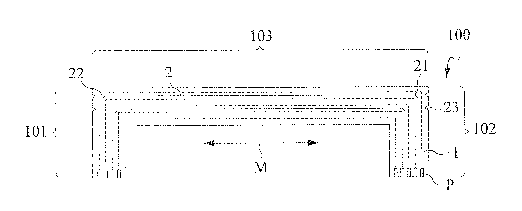
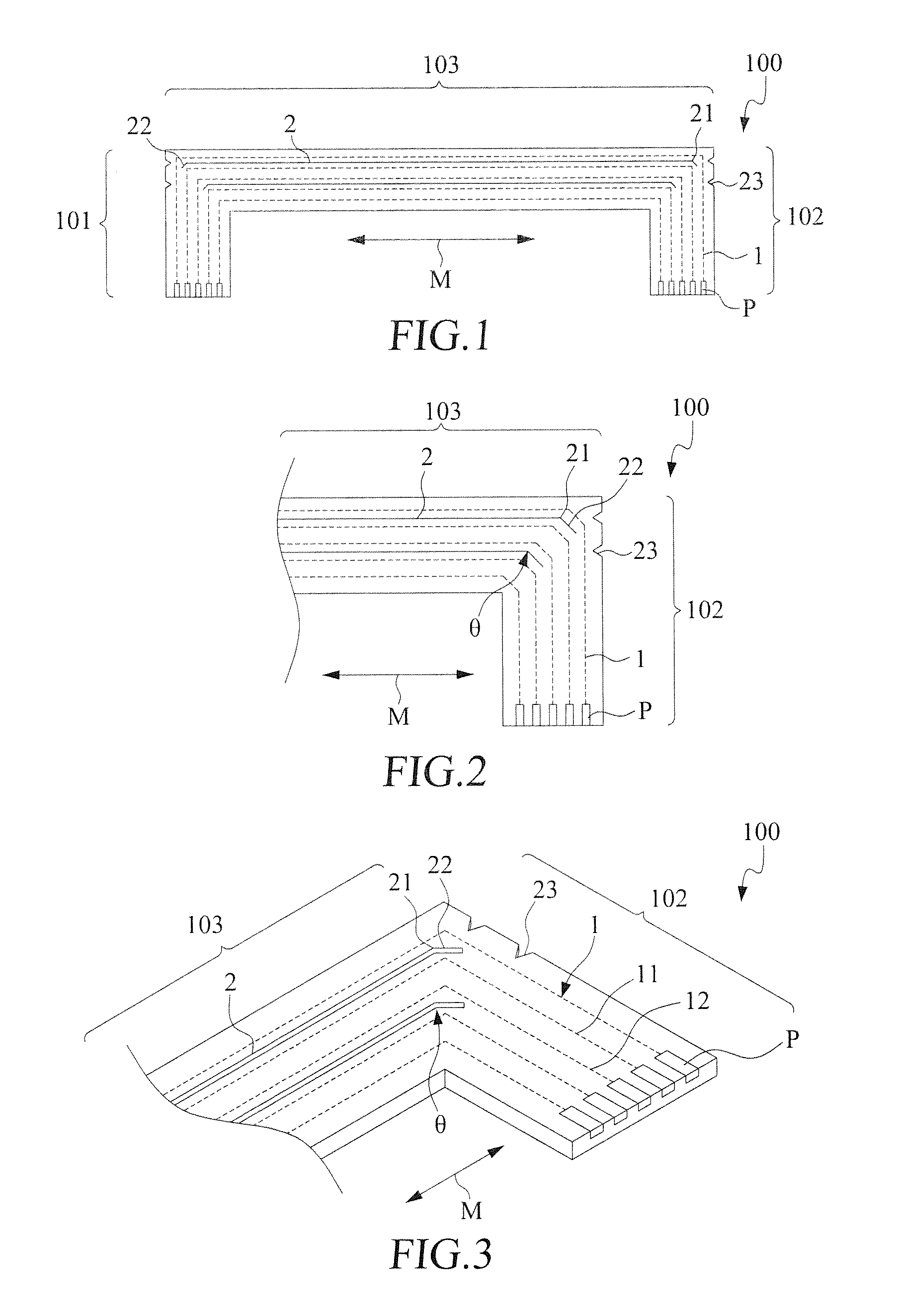
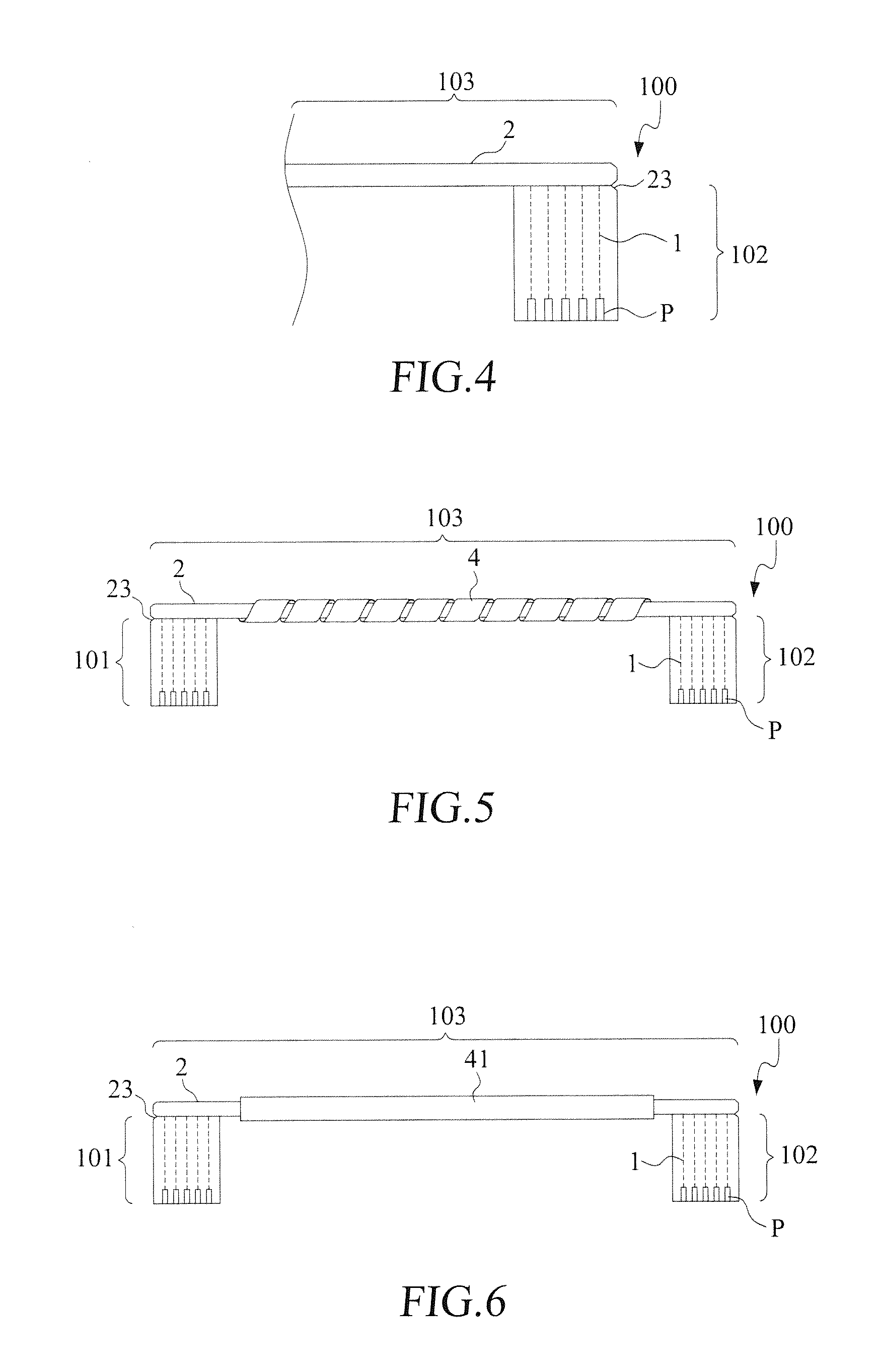
[0025]With reference to the drawings and in particular to FIGS. 1 and 2, of which FIG. 1 is a schematic view showing the present invention and FIG. 2 is an enlarged view showing a portion of FIG. 1, as shown in the drawings, a flexible circuit board 100 comprises a first connection section 101, a second connection section 102, and an extension section 103 connecting between the first connection section 101 and the second connection section 102. The extension section 103 extends in an extension direction M.

[0026]The extension section 103 comprises a plurality of conductor lines 1 extending in the extension direction M. The conductor lines 1 are respectively connected to signal terminals P arranged at first and second ends. The conductor lines 1 may include a power line, a grounding line, and signal lines and may alternatively or additionally include at least a pair of differential-mode signal lines 11, 12 that are paired together for transmission of differential-mode signals.

[0027]Al...

second embodiment

[0034]Referring to FIG. 9, a schematic view is given to show the present invention, in which the stress-diverting cut segment 22 comprises a tear protection hole 5 formed in the termination end thereof. When the slit line 2 of the flexible circuit board 100 is subjected to a folding operation or stretching or simply in a manufacturing process of a product, besides being diverted by the stress-diverting cut segment 22, a stress induced may be further stopped by the tear protection hole 5 that serves as a stress stopping structure to provide an enhanced effect of tear protection.

third embodiment

[0035]In the previous embodiments. the stress-diverting cut segment 22 is in the form of a straight line and such a linear stress-diverting cut segment 22 extends in and along an area between two adjacent ones of the conductor lines 1. The stress-diverting cut segment 22 can alternatively be of other configurations. For example, in the present invention illustrated in FIG. 10, a curved stress-diverting cut segment 6 extends from at least one of the terminal ends 21 of the slit line 2 of the flexible circuit board 100 and can similarly serve as a tear protection structure of the flexible circuit board 100.


PUM


Abstract

Disclosed is a tear protection structure for a flexible circuit board. In an extension section of a flexible circuit board, at least a slit line is formed. The slit line has at least a terminal end from which a stress-diverting cut segment extends. The stress-diverting cut segment is formed by cutting in a cutting direction that defines an angle with respect to an extension direction of the extension section to serve as the tear protection structure of the flexible circuit board. The extension section of the flexible circuit board is foldable along the slit line. The stress-diverting cut segment may further include a tear protection hole formed in a termination end thereof.

Description

BACKGROUND OF THE INVENTION[0001]1. Field of the Invention[0002]The present invention relates to a structural design of a flexible circuit board, and in particular to a tear protection structure for a flexible circuit board.[0003]2. The Related Arts[0004]In each of a variety of electronic devices that are currently used, due to the amount of transmission through signal cables being increasingly large, the number of signal transmission lines is also ever increased. Among all currently employed techniques of signal transmission lines, flexible circuit boards are the most promising technique at present. The flexible circuit boards are featured for being light in weight and small in volume and are adaptable to assembling conditions for products having various outside configurations for a general purpose of increasing wire density to serve as circuit carrier for signal connection or component assembling. A flexible circuit board can be integrated or connected with active components, pass...

Claims


Application Information

Patent Timeline
Patent Type & Authority Applications(United States)
IPC IPC(8): H05K1/02H05K1/11
CPCH05K1/0271H05K1/028H05K1/118H05K1/0281H05K2201/2009H05K2201/09063H05K2201/09145H05K1/0277
Inventor SU, KUO-FUCHUO, CHIH-HENGLIN, GWUN-JIN
Owner ADVANCED FLEXIBLE CIRCUITS
Why Eureka
Try Eureka