Eureka AIR delivers breakthrough ideas for toughest innovation challenges, trusted by R&D personnel around the world.

Grid for illumination apparatus

Inactive Publication Date: 2012-04-26
SIGNIFY HLDG BV +1
View PDF4 Cites 2 Cited by
  • Summary
  • Abstract
  • Description
  • Claims
  • Application Information

AI Technical Summary

Benefits of technology

[0005]Inventors of the present invention have found that the electromagnetic radiation from a light source may cause danger to the users, especially the users who are very close to the light source; it would therefore be advantageous to reduce or prevent the electromagnetic radiation from the light source.
[0009]The basic idea is to attenuate the electromagnetic radiation from the light source by using the waveguide formed by the electro conductive baffles. Since the waveguide has a cut-off frequency, if the electromagnetic radiation has a frequency below the cut-off frequency, the electromagnetic radiation is attenuated exponentially when it travels along the waveguide. Therefore, by rationally designing the waveguide formed by the cells, the electromagnetic radiation from the light source can be effectively attenuated, and then the electromagnetic radiation from the light source is reduced or prevented to decrease the danger to users. At the same time, the grid has a certain depth which can narrow the radiation angle of the light from the light source to reduce the glare caused by direct light emission into users' eyes.
[0012]By placing the grid at one side of the light source, which can reduce or prevent the electromagnetic radiation from the light source, the electromagnetic radiation is reduced at the other side of the grid as a result of passing through the grid, and less danger is caused to the users of the luminaire. In addition, the radiation angle of the light passing through the grid becomes narrow and then glare caused by direct light emission into users' eyes is reduced.

Problems solved by technology

Inevitably, high-frequency ballasts can lead to electromagnetic radiation.
Environmental-protection experts point out that excessive amounts of electromagnetic radiation can lead to palpitation, insomnia, memory degradation, and even reduction of immunity, as well as damage to the heart, the blood circulation system and the neural system.
The illuminator grid disclosed in U.S. Pat. No. 3,774,024 can only mask the glare of a light source from direct view, but cannot reduce or prevent the electromagnetic radiation from the light source.

Method used


Image

  • Grid for illumination apparatus
  • Grid for illumination apparatus
  • Grid for illumination apparatus

Examples


Embodiment Construction

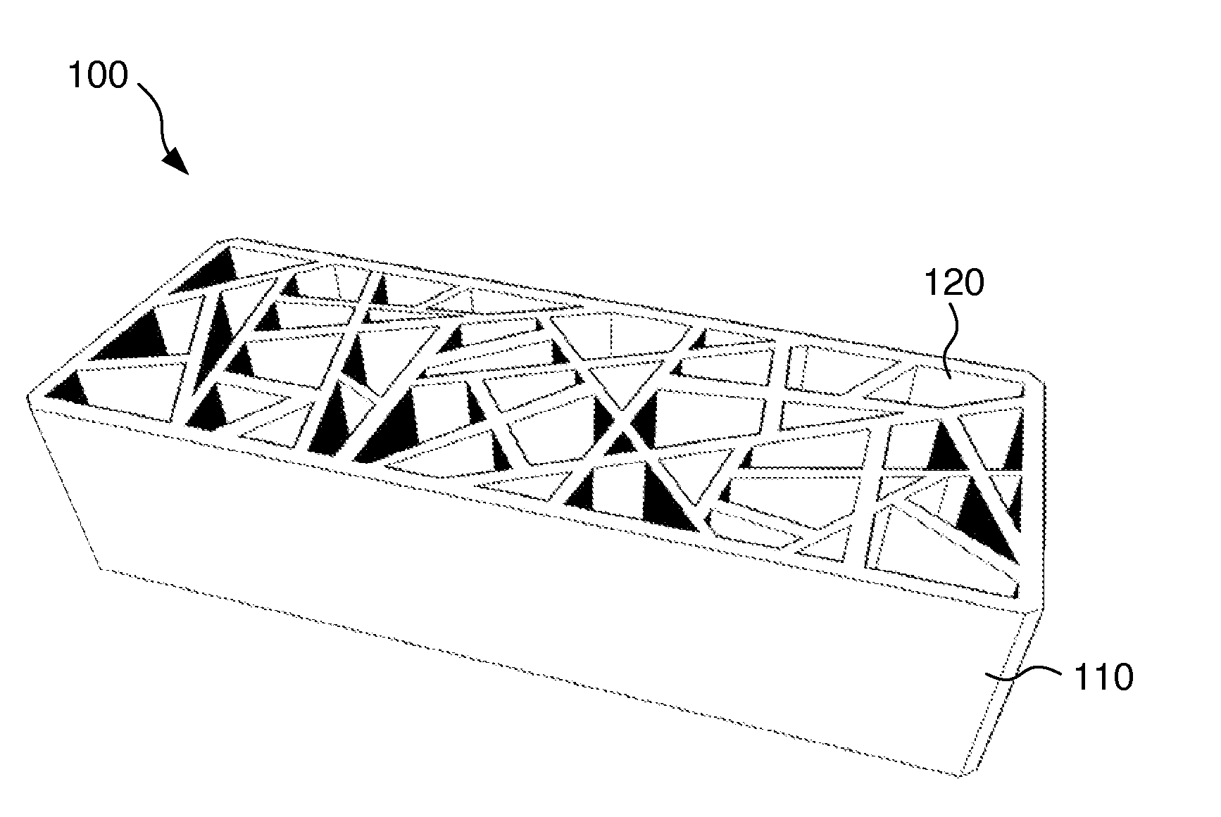
[0020]Firstly, there is provided a grid 100 for attenuating electromagnetic radiation from a light source.

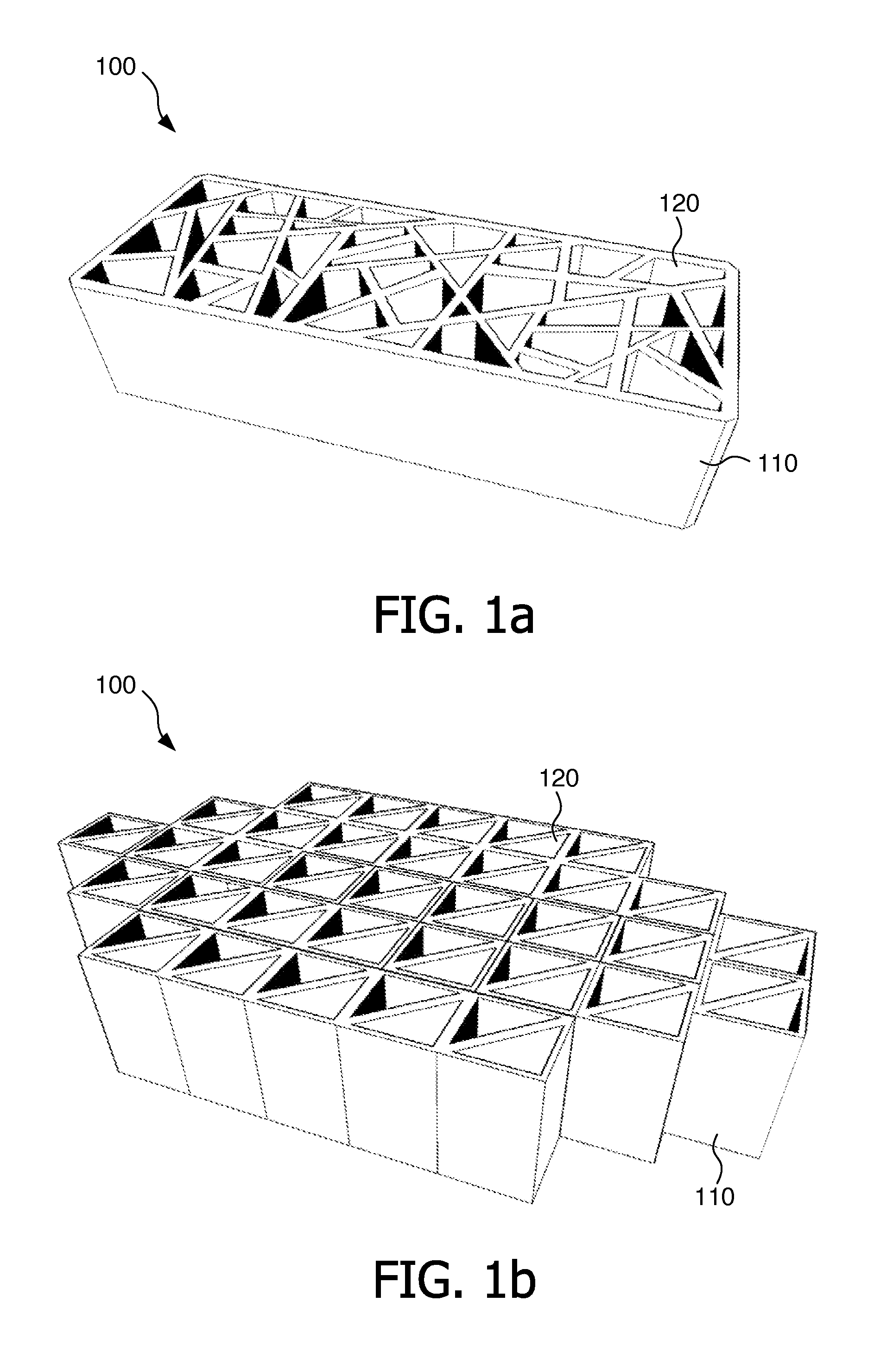
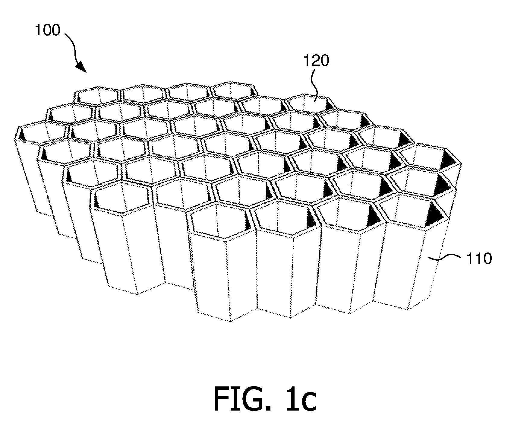
[0021]FIG. 1 (a) to FIG. 1 (c) depict schematic diagrams of embodiments of the grid.

[0022]The grid comprises a plurality of baffles 110, each baffle 110 being electro conductive.

[0023]The electro conductive baffle 110 can be made in many ways, for example, by using an electro conductive material, such as copper, aluminum and iron, or covering the baffle 110 with an electro conductive material. The thickness of the electro conductive material covering the baffle 110 can be determined by using the following equation:

δ=2ρωμ,

wherein δ is the skin depth, i.e., the minimum thickness of the electro conductive material covering the baffle 110, ω is the angular frequency of the electromagnetic wave to be attenuated, and μ is the absolute permeability of the electro conductive material.

[0024]Referring to FIG. 1 (a) to FIG. 1 (c), the plurality of baffles 110 are configured to form a plura...


PUM


Abstract

The invention relates to illumination, especially to a grid for illumination apparatus. This invention provides a grid (100) for attenuating electromagnetic radiation from a light source. The grid comprises a plurality of baffles (110), each baffle being electro conductive, wherein the plurality of baffles are configured to form a plurality of cells (120), each cell being formed as a waveguide so as to attenuate the electromagnetic radiation from the light source. In this way, the electromagnetic radiation from the light source can be reduced or prevented so as to decrease the danger to users.

Description

FIELD OF THE INVENTION[0001]The invention relates to illumination, especially to a grid for illumination apparatus.BACKGROUND OF THE INVENTION[0002]To overcome 100 Hz light flickering of fluorescent lamps working at 100 Hz alternating current, high-frequency eye care lamps employ a working frequency in the range of 40 kHz to 55 kHz. Inevitably, high-frequency ballasts can lead to electromagnetic radiation. If no action is taken, it is possible that high-frequency electromagnetic radiation is emitted to the outside world. Environmental-protection experts point out that excessive amounts of electromagnetic radiation can lead to palpitation, insomnia, memory degradation, and even reduction of immunity, as well as damage to the heart, the blood circulation system and the neural system. The public has come to the consensus that more protection can reduce the danger from electromagnetic radiation.[0003]U.S. Pat. No. 3,774,024 discloses an illuminator grid adapted to be disposed beneath a ...

Claims


Application Information

Patent Timeline
IPC IPC(8): H01J1/52F21Y101/00
CPCF21V11/06H05K9/0041F21Y2103/00F21V25/00
Inventor LIU, YONGYIP, KUN-WAHLOU, DI
Owner SIGNIFY HLDG BV
Why Eureka
Eureka Blog
Learn More