Light source control device, projector, and light source control method
- Summary
- Abstract
- Description
- Claims
- Application Information
AI Technical Summary
Benefits of technology
Problems solved by technology
Method used
Image


Examples
first embodiment
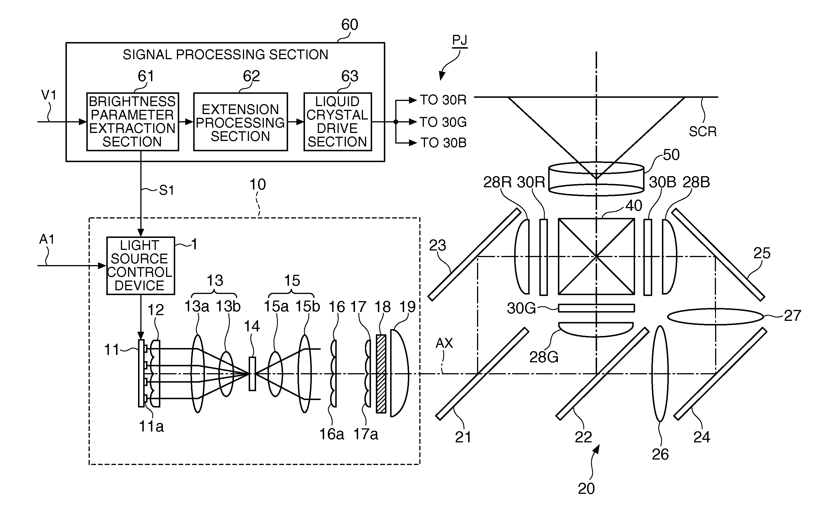
[0033]FIG. 1 is a block diagram showing a configuration of a substantial part of a light source control device according to a first embodiment of the invention. As shown in FIG. 1, the light source control device 1 according to the present embodiment is provided with a duty ratio determination section 2 (a determination section), a PWM signal generation section 3 (a drive control section), and light source drive sections 4a through 4d (the drive control section), and controls the drive of a solid-state light source array 11 (a light source device) based on a target light intensity signal S1 input externally. Here, the target light intensity signal S1 is a signal representing the target light intensity as the light intensity of the light to be emitted from the solid-state light source array 11. It should be noted that the target light intensity signal S1 can be a signal representing the brightness of the light to be emitted from the solid-state light source array 11.
[0034]As shown in...
second embodiment
[0049]FIG. 3 is a block diagram showing a configuration of a substantial part of a light source control device according to a second embodiment of the invention. As shown in FIG. 3, the light source control device 1′ according to the present embodiment has the configuration obtained by adding a drive current control section 6 (a current control section) to the light source control device 1 shown in FIG. 1, replacing the duty ratio determination section 2 with a duty ratio selection section 5 (the determination section), and replacing the light source drive sections 4a through 4d with light source drive sections 7a through 7d (the drive control section). The light source control device 1′ having such a configuration is capable of varying the current values of the drive signals D1 through D4 to be supplied to the solid-state light source array 11 in accordance with the duty ratio selected by the duty ratio selection section 5.
[0050]The duty ratio selection section 5 selects the duty r...
third embodiment
[0066]FIG. 5 is a block diagram showing a configuration of a substantial part of a light source control device according to a third embodiment of the invention. As shown in FIG. 5, the light source control device 1″ according to the present embodiment is provided with a polarity reversal signal generation section 8 (the drive control section) and lamp drive sections 9a, 9b, and controls drive of the lamp unit U (the light source device) having a plurality of lamps U1, U2 while reversing the polarity of the applied voltage.
[0067]The light source control devices 1, 1′ of the first and second embodiments are for controlling the solid-state light sources 11a on which instant lighting and instant extinction can be performed. In contrast thereto, the light source control device 1″ according to the present embodiment is for controlling the lamps U1, U2 requiring several minutes of time for relighting after once put off. The lamps U1, U2 provided to the lamp unit U are discharge lamps such ...
PUM
 Abstract
Description
Claims
Application Information
 - R&D
- Intellectual Property
- Life Sciences
- Materials
- Tech Scout
- Unparalleled Data Quality
- Higher Quality Content
- 60% Fewer Hallucinations
Browse by: Latest US Patents, China's latest patents, Technical Efficacy Thesaurus, Application Domain, Technology Topic, Popular Technical Reports.
© 2025 PatSnap. All rights reserved.Legal|Privacy policy|Modern Slavery Act Transparency Statement|Sitemap|About US| Contact US: help@patsnap.com