Fluid directing system for turbines

a technology of fluid directing system and turbine, which is applied in the direction of engine control parameters, working fluid for engines, motors, etc., can solve the problems of increasing the power generated by the blades once the rated velocity is exceeded, reducing the swept area of the rotor, and reducing the useful energy of the engine, so as to achieve the effect of increasing the fluid directing pressure over the high torque area, reducing the swept area of the rotor, and increasing the speed of the fluid

Inactive Publication Date: 2012-04-26
ORGANOWORLD
View PDF15 Cites 31 Cited by
  • Summary
  • Abstract
  • Description
  • Claims
  • Application Information

AI Technical Summary

Benefits of technology

[0038]For both the axial and cross-flow turbines, the velocity pressure of the fluid stream over the high torque area is increased providing considerable more power. Although the swept area of the rotors has been decreased, the increase in fluid velocity or velocity pressure provides a much greater contribution to energy production. The adjustment of the swept area also controls the fluid stream velocity to the blades providing maximum efficiency for the rotor at all nominal fluid speeds. The control of the fluid stream speed in turn provides for steady rotor rotational speeds for more stable and efficient electrical power generation.

Problems solved by technology

Low winds contain less energy than high winds so automatically they produce less useful energy.
The additional power generated by the blades once the rated velocity is exceeded is lost.
The fact that wind speeds vary all the time is a problem for windmill designers and windmill operators.
Existing wind turbines designs offer little control over immediate wind speed variations.
At all wind speeds, and particularly at high wind speeds, wind gusts cause considerable operating problems.
This can cause voltage fluctuations in the power produced that must be removed electrically.
In order to limit the rotational speed, the blade pitch can be adjusted but the blades are massive and the hydraulically driven pitch adjustment is not rapid.
The energy of the wind traveling close to the center shaft or the core of the swept area is essentially wasted.

Method used


Image

  • Fluid directing system for turbines
  • Fluid directing system for turbines
  • Fluid directing system for turbines

Examples


example 1

A VAWT and Sectored Rotor at 4.0 m / s

[0178]At 4.0 m / s the sectoring ratio was varied between 1.0 and 0.67. The power produced increased from 10 to 35 kW or an increase of 3.5 fold.

example 2

A VAWT and Sectored Rotor at 7.0 m / s

[0179]At 7.0 m / s the sectoring ratio was varied between 1.0 and 0.67. The power produced increased from 50 to 120 kW or an increase of 2.5 fold.

example 3

A VAWT and Sectored Rotor at 12.0 m / s

[0180]At 12.0 m / s the sectoring ratio was varied between 1.0 and 0.67. The power produced increased from 200 to 625 kW or an increase of 3.1 fold.

[0181]The results obtained are shown as curves in FIG. 19.

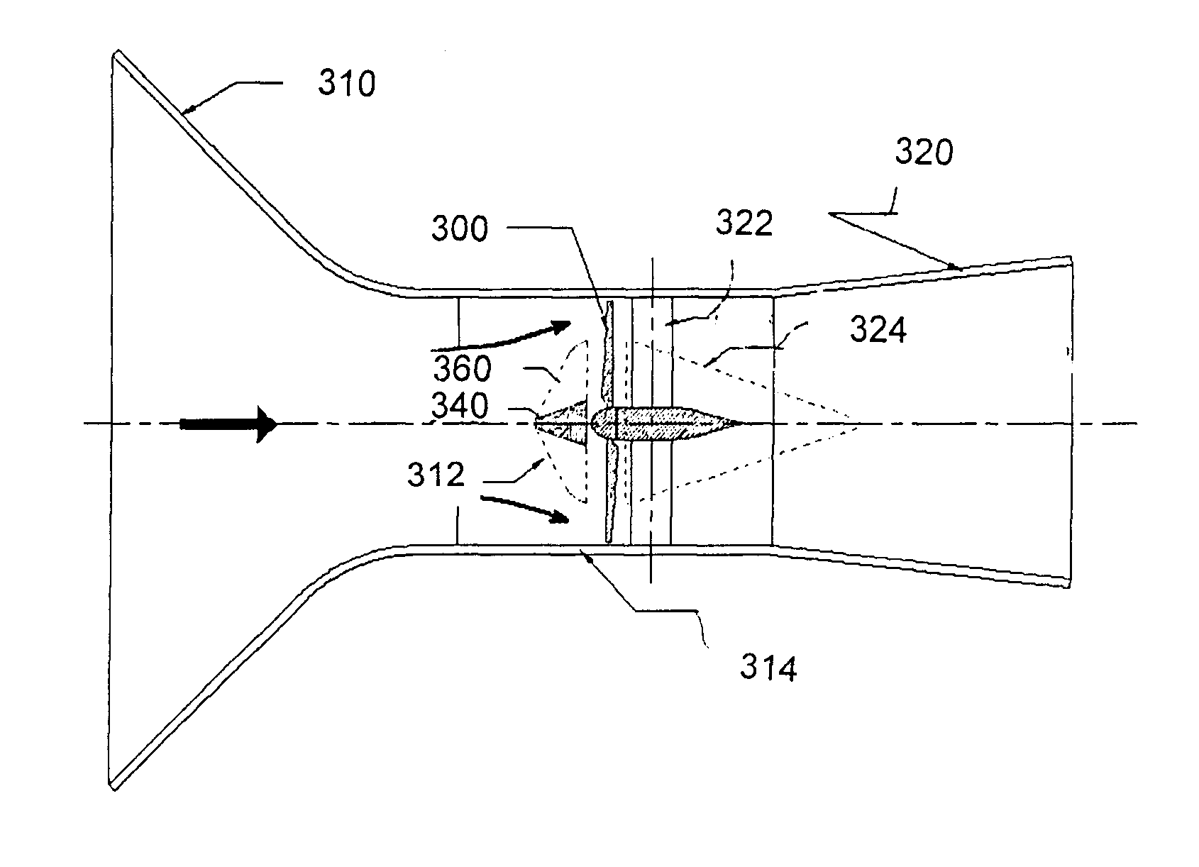
[0182]As a person skilled in the art would understand a plurality of types of cross-flow or vertical axis turbines may be used with the device of the present invention. Also for each wind turbine different combinations may be used for example a different number and / or configuration of blades, the space between the wind section and the wind turbine, etc.

[0183]As a person skilled in the art would understand the parameters of the sectoring cone may differ from the examples shown in this document. Similarly the mechanism for adjusting the opening of the aperture or flow channel may differ based on the fluids, operating conditions and turbine apparatus.


PUM


Abstract

A directing system for directing fluid entering an axial flow turbine along an inlet flow direction. The turbine includes a plurality of turbine blades. The directing system includes a base structure, a plurality of directing segments attached to the base structure, downstream of the base structure, and a directing segment adjustment system for adjustably positioning the directing segments between a retracted configuration and a deployed configuration. The directing segments, in the deployed configuration, extend beyond the base structure in a direction transversal to the inlet flow direction and deflect the fluid towards an outer circumference of the plurality of turbine blades corresponding to a higher torque area of the blades. A directing system for directing fluid entering a cross-flow turbine is also disclosed. In the cross-flow turbine, the fluid is directed towards a centerline of the rotor of the turbine, which is a high torque area of the turbine blades.

Description

FIELD OF THE INVENTION[0001]The present invention generally relates to both wind and water turbines. More specifically, the present invention relates to a fluid directing system for directing a fluid entering an axial flow or cross-flow turbine.BACKGROUND OF THE INVENTION[0002]Wind turbines are generally rated at the wind speed at which they will produce the rated power or essentially the maximum power rating of the generator. At lower wind velocities the turbine will produce only a fraction of the rated power.[0003]Low winds contain less energy than high winds so automatically they produce less useful energy. The rotor efficiency or percentage of energy converted from the wind into useful torque also drops as the Reynolds number of the blades decreases at low wind speeds. There is a definite need for a rotor design that could increase the power obtained from air streams at all speeds and most particularly for velocities below the turbine rated speed. The additional power generated ...

Claims


Application Information

Patent Timeline
Patent Type & Authority Applications(United States)
IPC IPC(8): F01D9/02F01D1/04
CPCF03B17/061F05B2270/32F03D1/04F05B2210/16Y02E10/28Y02E10/721Y02E10/223Y02E10/226F03B3/183F03B15/08F05B2240/121F05B2240/211F05B2240/217F05B2240/221F05B2240/244F05B2270/1014F03B17/062Y02E10/20Y02E10/72
Inventor CHURCHILL, FREDERICKPARASCHIVOIU, IONTRIFU, OCTAVIAN
Owner ORGANOWORLD
Why Eureka
Try Eureka