
Method and controller for controlling output torque of a propulsion unit

Active Publication Date: 2012-04-26
VOLVO LASTVAGNAR AB
View PDF18 Cites 24 Cited by
  • Summary
  • Abstract
  • Description
  • Claims
  • Application Information

AI Technical Summary

Benefits of technology

[0005]In one known solution, model state reference trajectories of engine speed are generated. These reference trajectories are based on the registered change in accelerator pedal position, and are designed to provide a damped transition to a new torque request and a relatively smooth transition of the backlash. A power demand controller subsequently generates a compensated power demand to the engine according to the said generated reference trajectories, thereby reducing shuffle. A force transmission based on reference trajectories however leads to relatively low drivability in terms of quick response to driver torque demand with good damping of driveline oscillations.
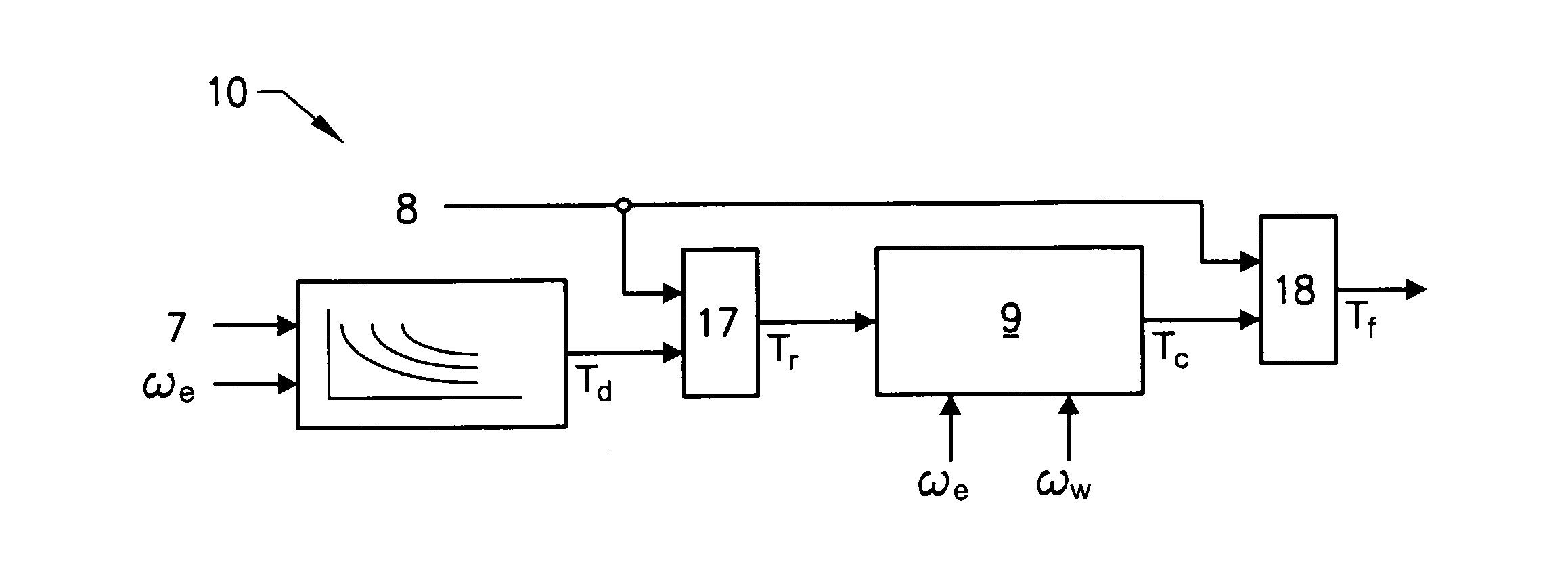
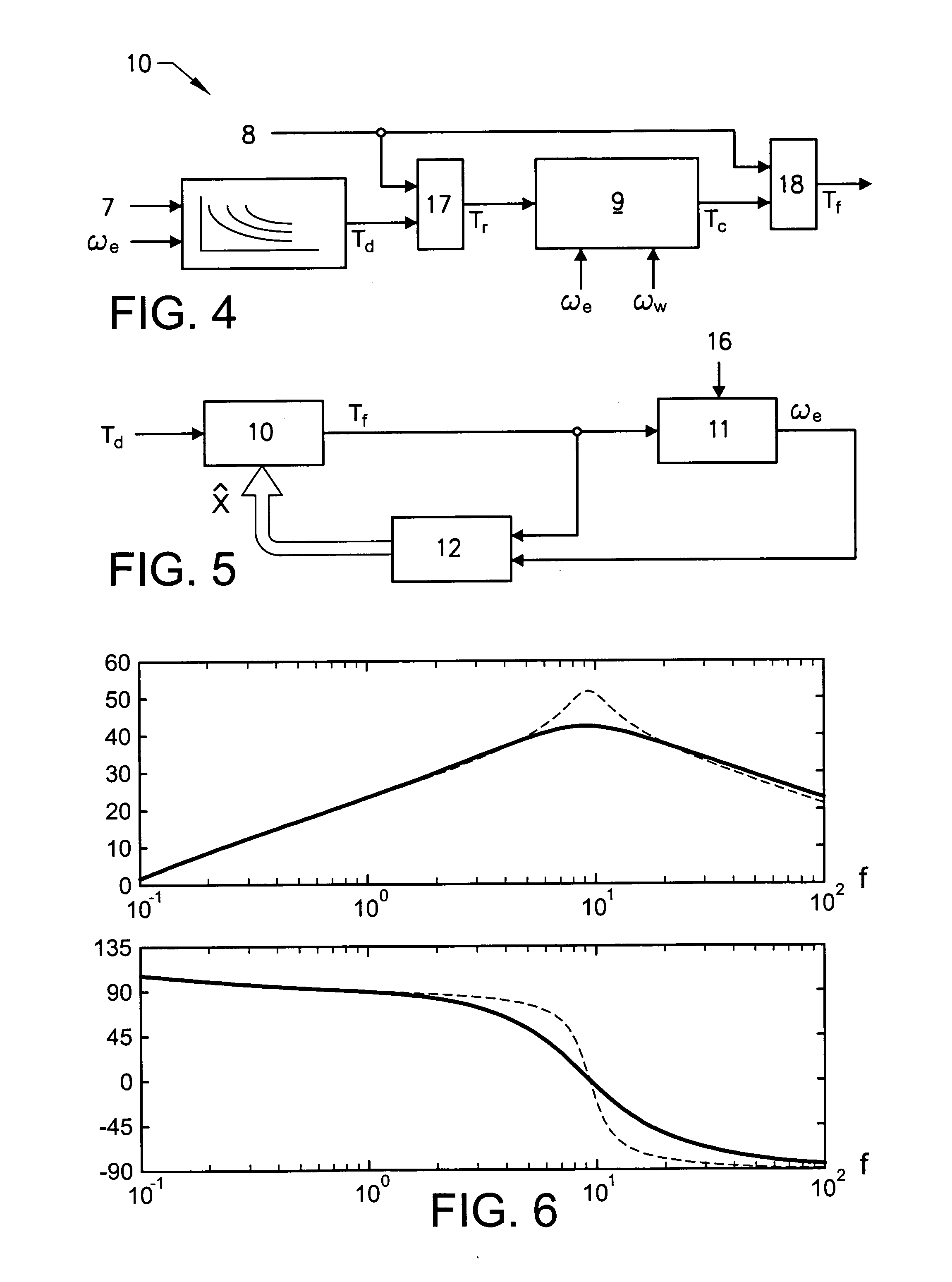
[0008]It is desirable to provide an inventive method and torque controller for controlling output torque of a propulsion unit where the previously mentioned problems are partly avoided. A method according to an aspect of the present invention comprises the steps of registering driver torque demand for vehicle propulsion, registering propulsion unit rotational speed, and controlling said output torque of said propulsion unit to asymptotically follow said driver torque demand. Controlling is performed using a closed-loop linear-quadratic regulator (LQR) based controller having said driver torque demand and said propulsion unit rotational speed as input data, with the aim to minimize driveline oscillations.
[0009]A controller according to an aspect of the present invention is a closed-loop linear-quadratic regulator (LQR) based controller, and wherein the controller is arranged to control the output torque of said propulsion unit by the steps of registering driver torque demand for vehicle propulsion, registering propulsion unit rotational speed, and controlling said output torque of said propulsion unit to asymptotically follow said driver torque demand having said driver torque demand and said propulsion unit rotational speed as input data, in order to minimize driveline oscillations.

Problems solved by technology

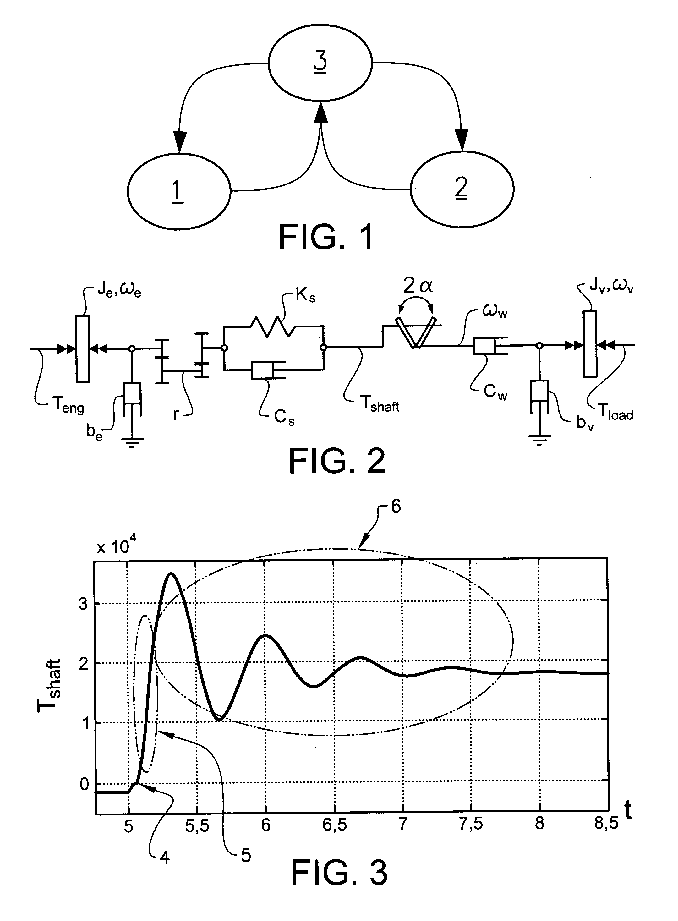
The oscillations caused by a pedal tip-in manoeuvre, where the driver for example quickly depresses the accelerator pedal negatively effects the perceived vehicle drivability, causing variations in the vehicle longitudinal tractive force, known as shuffle or vehicle jerking.
The vehicle powertrain also includes an inevitable backlash mainly due to gear play, which is caused by manufacturing tolerances in transmission and differential components.
When the direction of force transmission reverses, the presences of backlash causes temporary discontinuation of the force transmission in the powertrain followed by impulsive force transmission, so that an acceleration shock occurs.
A force transmission based on reference trajectories however leads to relatively low drivability in terms of quick response to driver torque demand with good damping of driveline oscillations.
This solution however does not solve the problem of shuffle, and none of the presented prior art solutions take into account varying parameters of the system and its environment, thus requiring careful tuning and calibration of the system to function properly.

Method used


Image

  • Method and controller for controlling output torque of a propulsion unit
  • Method and controller for controlling output torque of a propulsion unit
  • Method and controller for controlling output torque of a propulsion unit

Examples


Embodiment Construction

[0023]The inventive method and torque controller for controlling output torque of a propulsion unit uses a closed-loop linear-quadratic regulator (LQR) based torque controller for damping driveline oscillations in an automotive driveline. The developed controller has the attractive feature of fitting very well into the archetypical heavy truck engine control system of today, being based on torque control. Thus, the controller can easily be incorporated as an additional torque compensator. The inventive method and controller is suitable for controlling output torque of different types of propulsion units, such as diesel engines, spark ignition engines, and electric motors. The torque control of the LQR controller is particularly advantageous for propulsion units having fast torque response, such as a diesel engine, because of the optimal control with respect to quick response to driver torque demand while maintaining good damping of driveline oscillations.

[0024]The controller damps d...


PUM


Abstract

Method for controlling output torque (Teng) of a propulsion unit in a vehicle powertrain including driven wheels drivingly connected to the propulsion unit via a mechanical transmission with a drive shaft, wherein the method including the steps of registering driver torque demand (Td) for vehicle propulsion, registering propulsion unit rotational speed (ωe), and controlling the output torque (Teng) of the propulsion unit to asymptotically follow the driver torque demand (Td) using a closed-loop linear-quadratic regulator (LQR) based controller (9) having the driver torque demand (Td) and the propulsion unit rotational speed (ωe) as input data, in order to minimize driveline oscillations.

Description

[0001]The present application is the U.S. national stage of International Application PCT / EP2010 / 003986, filed 5 Jul. 2010, which claims priority to U.S. Provisional Application 61 / 223,428, filed 7 Jul. 2009, both of which are incorporated by reference.BACKGROUND AND SUMMARY[0002]The present invention relates to a method for controlling output torque of a propulsion unit in a vehicle powertrain comprising driven wheels drivingly connected to the propulsion unit via a mechanical transmission with a drive shaft, and to a corresponding controller.[0003]It is known that an automotive powertrain is a naturally light-damped oscillatory system that will generate oscillations in response to a rapid change of force transmission. The oscillations caused by a pedal tip-in manoeuvre, where the driver for example quickly depresses the accelerator pedal negatively effects the perceived vehicle drivability, causing variations in the vehicle longitudinal tractive force, known as shuffle or vehicle ...

Claims


Application Information

Patent Timeline
IPC IPC(8): B60W10/04B60W30/18
CPCB60W30/20
Inventor TEMPLIN, PETER
Owner VOLVO LASTVAGNAR AB
Learn More