Mount for pitched roof and method of use

Inactive Publication Date: 2012-05-03
DYNORAXX
View PDF31 Cites 142 Cited by
  • Summary
  • Abstract
  • Description
  • Claims
  • Application Information

AI Technical Summary

Problems solved by technology

A significant part of the cost of a solar panel system is the installation cost and the cost of the racking system.
However, securing a sy

Method used


Image

  • Mount for pitched roof and method of use
  • Mount for pitched roof and method of use
  • Mount for pitched roof and method of use

Examples


Embodiment Construction

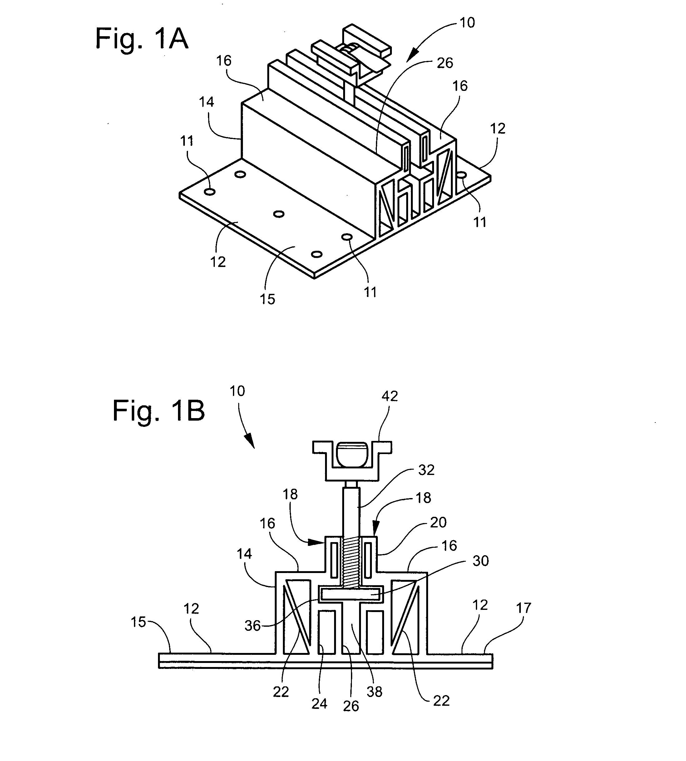
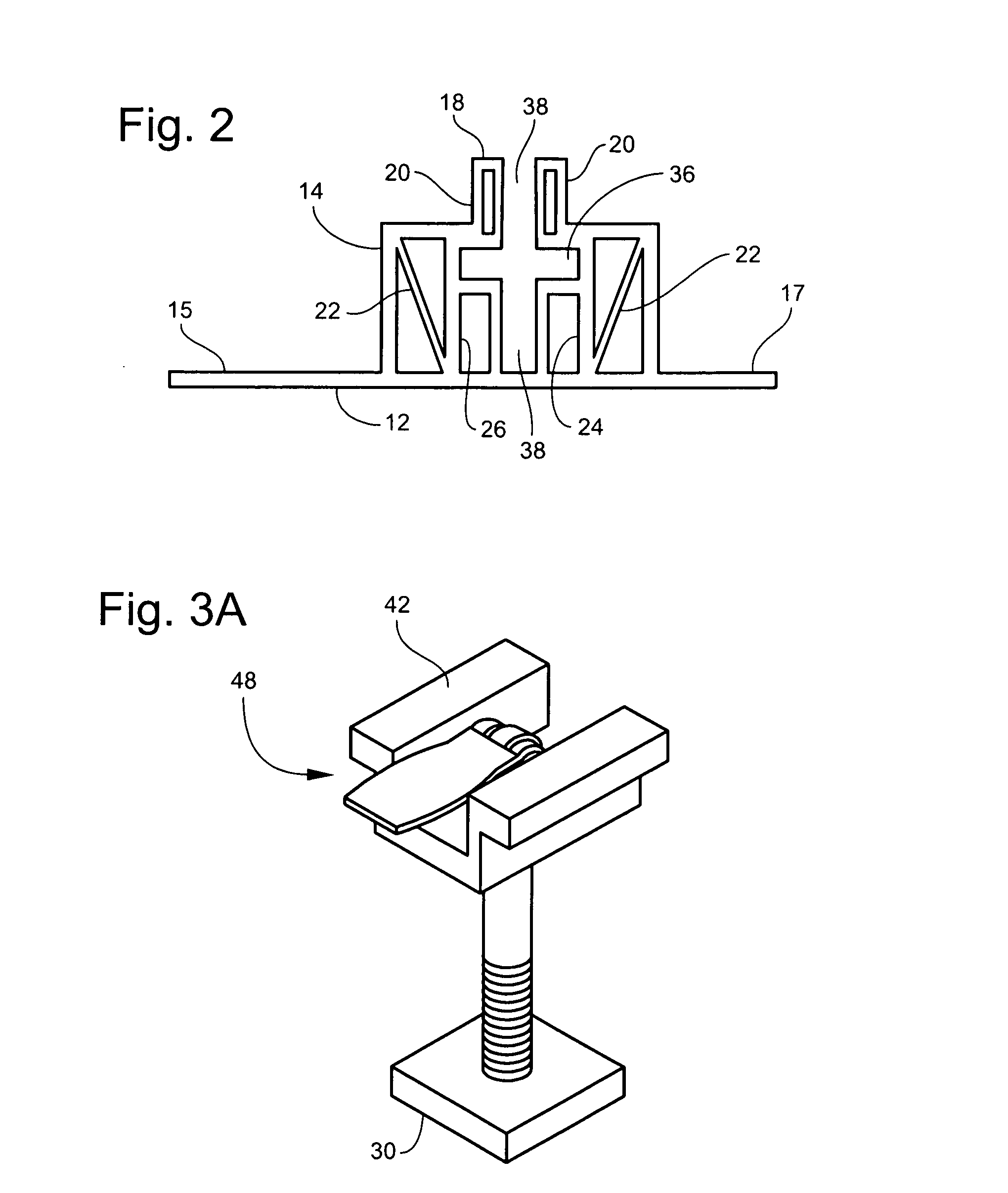
[0068]Reference is made to FIGS. 1A-1E and FIG. 2 which show an embodiment of the clamping mechanism of another embodiment of the present invention. FIG. 1A-1E shows a photovoltaic mount 10 of one embodiment. The mount includes a base plate 12 that is placed on the roof at a desired location to support and secure a photovoltaic panel (not shown) to a roof including a pitched roof.

[0069]The base plate 12 is secured to the roof by a plurality of fasteners received through the holes 11 in the base plate 12. Preferably, wood screws are used to secure the plate 12 to the roof. In another preferred embodiment, deck screws are used so that the plate can be affixed to any location on the deck and the base plate 12 does not have to be positioned over a roof rafter or beam. In one embodiment, a first side 15 of the base plate 12 has a sufficient number of holes to safely and adequately secure the entire mount on the first side 15 without requiring screws on the second side 17. In one embodime...


PUM


Abstract

In one embodiment, there is a mount for a pitched roof. The mount comprises a fastening plate. The fastening plate includes at least one support extending upwardly from the fastening plate to support a pair of mounting surfaces a predetermined distance above the pitched roof. At least a portion of the fastening plate extends laterally from the one or more supports. The pair of mounting surfaces is configured to support at least one photovoltaic panel. The mount further includes a clamp housing between the pair of mounting surfaces and receives a clamp. The clamp comprises a pair of laterally extending clamp plates and at least one clamp stabilizer configured to prevent the clamp plate from tilting when the clamping force is applied.

Description

CROSS-REFERENCE TO RELATED APPLICATIONS[0001]The present application claims the benefit of U.S. Provisional Application 61 / 404,618 filed Oct. 5, 2010 and U.S. Provisional Application 61 / 431,112 filed Jan. 10, 2011. Both of these applications are incorporated by reference herein in their entirety.BACKGROUND OF THE INVENTION[0002]1. Field of the Invention[0003]This invention relates to devices, systems and methods for mounting solar panels on a pitched roof.[0004]2. Discussion of State of the Art[0005]There is a growing market for alternative energy. Alternative energy includes energy that is generated from wind turbines, water powered turbines, and energy from the sun. Alternative energy not only potentially provides cleaner sources of energy that are good for the environment, but the relative low cost of operating and maintaining an alternative energy system, such as a photovoltaic power system, has given an individual home owner the ability to generate his own power at a cost that ...

Claims


Application Information

Patent Timeline
IPC IPC(8): E04D13/18E04B1/38
CPCF24J2/5207F24J2/5245F24J2/5258H02S20/23Y02B10/12Y02E10/47Y02B10/20F24S25/61F24S25/35F24S25/636Y02E10/50Y02B10/10
Inventor RIZZO, NATHAN
Owner DYNORAXX
Why Eureka
Try Eureka