Drive assembly for an electric motorcycle, and electric motorcycle incorporating same

a technology for electric motorcycles and drive assemblies, applied in the direction of magnetic circuit rotating parts, magnetic circuit shapes/forms/construction, cycle equipments, etc., can solve problems such as complicated installation work, and achieve the effects of centralizing the mass, improving installation work, and protecting electric motors and batteries effectively

Active Publication Date: 2012-05-03
HONDA MOTOR CO LTD
View PDF6 Cites 61 Cited by
  • Summary
  • Abstract
  • Description
  • Claims
  • Application Information

AI Technical Summary

Benefits of technology

[0016]According to the first aspect of the present invention, since the battery is disposed at a position located forward and upward of the electric motor, it is possible to put together and compactly dispose the relatively heavy electric motor and battery, which enables to centralize the mass in the vehicle body. In addition, the drive assembly is composed for accommodating the electric motor and the battery in the case member, which thereby can improve the installation work and protect the electric motor and the battery effectively.
[0017]According to the second aspect of the present invention, since the drive assembly is provided with the motor driver arranged below the electric motor and the battery, it is possible to further centralize the mass in the vehicle body and to further improve the installation work. Additionally, the motor driver is mounted on the lower surface of the case member, which thereby enables to remove and install the motor driver readily and easily facilitate the maintenance of the motor driver.
[0018]According to the third aspect of the present invention, due to the fact that the protective frame of the body frame longitudinally extends on the lower side of the motor driver, it is possible to protect the motor driver from hitting the ground.
[0019]According to the fourth aspect of the present invention, due to the fact that the front surface of the case member is formed with the first fins extending vertically, it is possible to flow the driving wind colliding with the front surface of the case member toward the motor driver mounted on the lower surface of the case member, which thereby enables to cool the motor driver efficiently.
[0020]According to the fifth aspect of the present invention, due to the fact that the lower surface of the motor driver is formed with the second fins extending longitudinally, it is possible to flow the driving wind from the front to the rear of the motor driver, which thereby enables to cool the motor driver efficiently.
[0021]According to the sixth aspect of the present invention, during operation, air is taken in from the intake ports which are formed to the upper portion on front side of the case member, is flown rearward and downward within the case member and is discharged from the exhaust port which is formed to the lower portion on rear side of the case member. Thus, it is possible to cool the electric motor and the battery in the case member efficiently.

Problems solved by technology

However, in the electric motorcycle of Japanese Publication H5-105176 an electric motor and a battery, which are relatively heavy in weight, are separately disposed as described above, and this design has a problem in that the heavy portions in the vehicle body are dispersed on the frame, and the installation work is complicated.

Method used


Image

  • Drive assembly for an electric motorcycle, and electric motorcycle incorporating same
  • Drive assembly for an electric motorcycle, and electric motorcycle incorporating same
  • Drive assembly for an electric motorcycle, and electric motorcycle incorporating same

Examples


Embodiment Construction

[0031]An illustrative embodiment of the present invention will now be described, with reference to the drawings. Throughout this description, relative terms like “upper”, “lower”, “above”, “below”, “front”, “back”, and the like are used in reference to a vantage point of an operator of the vehicle, seated on the driver's seat and facing forward. It should be understood that these terms are used for purposes of illustration, and are not intended to limit the invention.

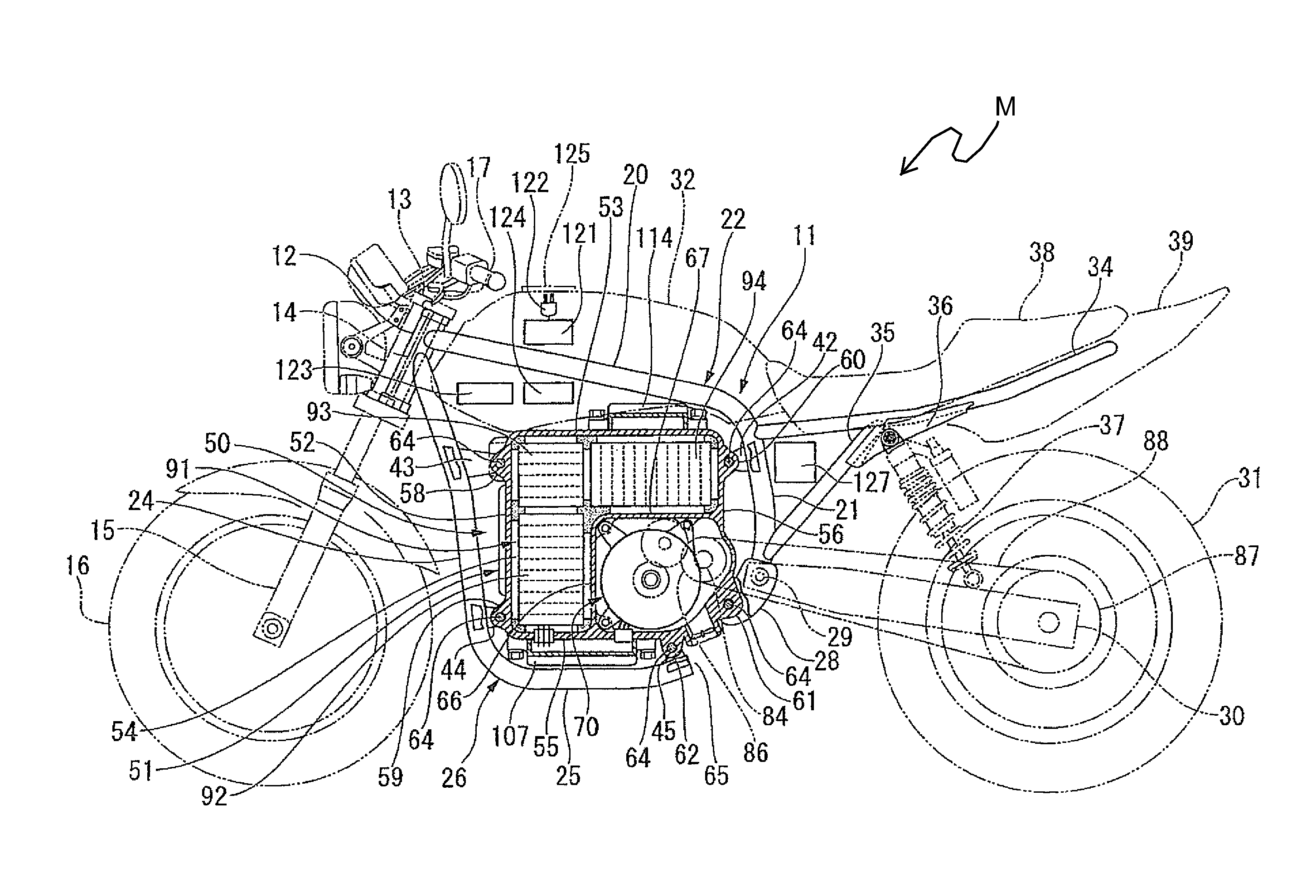
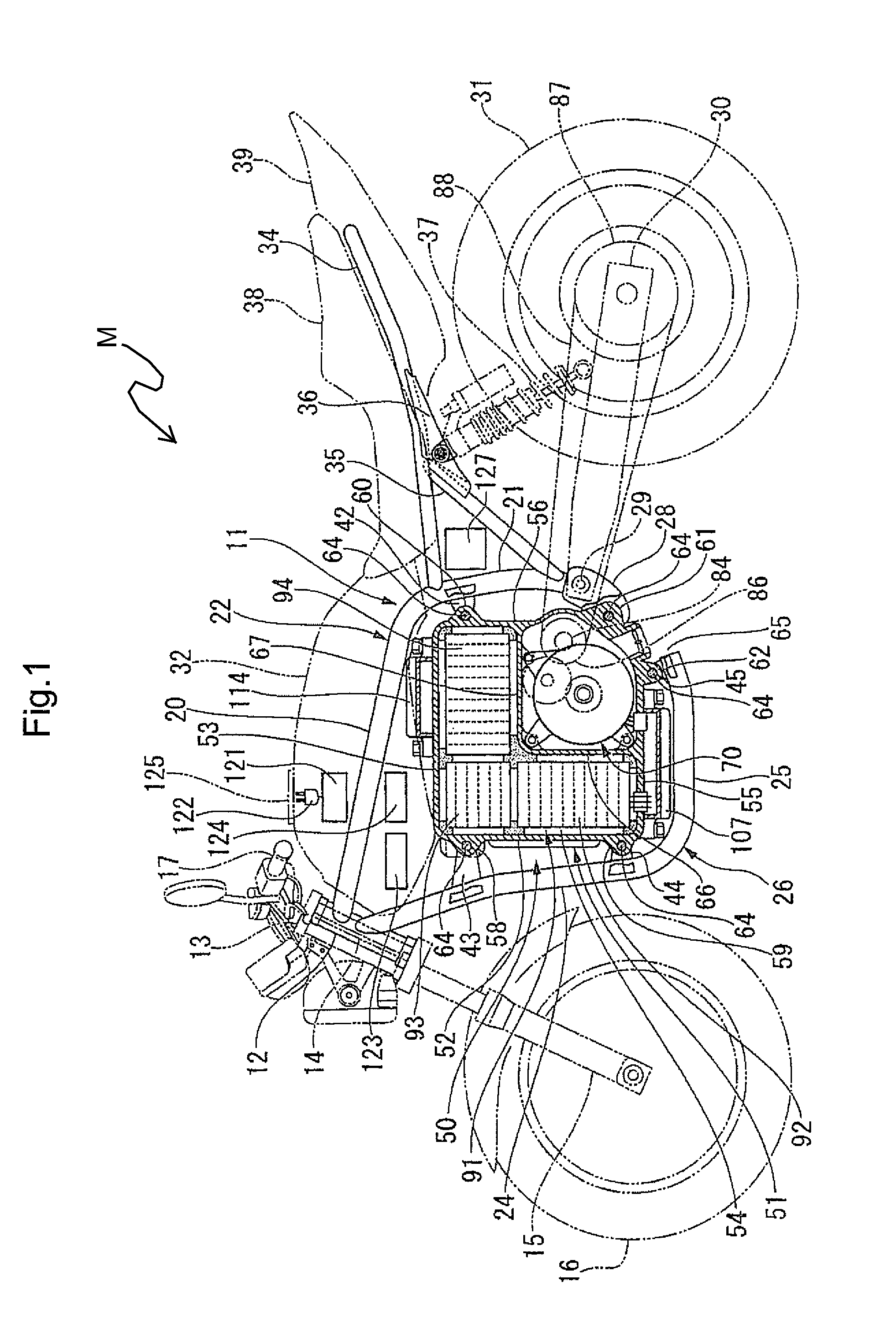
[0032]Hereinafter, an electric motorcycle M according to the illustrative embodiment of the present invention will now be described with reference to drawings FIGS. 1-7.

[0033]As shown in FIG. 1, the electric motorcycle M according to the present invention includes a steering shaft 14 provided on a stem 13. The steering shaft is rotatably and pivotally supported in a head pipe 12 provided on the front end of a body frame 11. A pair of left and right front forks 15 is attached to the stem 13. A front wheel 16 is pivotally...


PUM


Abstract

An electric motorcycle includes an electric motor for generating a traveling driving force, a battery for supplying electricity to the electric motor, and a case member for accommodating the electric motor and the battery therein. The battery includes a plurality of battery modules, which are disposed in the case member at positions forward of and above of the electric motor. Such arrangement of the electric motor and the battery in the case member helps to centralize mass in a vehicle body of the motorcycle, as well as simplifying assembly of the motorcycle.

Description

CROSS-REFERENCE TO RELATED APPLICATIONS[0001]The present invention claims priority under 35 USC 119 based on Japanese patent application No. 2010-243975, filed on Oct. 29, 2010. The entire subject matter of this priority document, including specification claims and drawings thereof, is incorporated by reference herein.BACKGROUND OF THE INVENTION[0002]1. Field of the Invention[0003]The present invention relates to an electric motorcycle. More particularly, the present invention relates to a drive assembly, including an electric motor and battery for an electric motorcycle, and to an electric motorcycle incorporating the drive assembly.[0004]2. Description of the Background Art[0005]There is a known electric motorcycle in which an electric motor, for generating a traveling driving force, is disposed substantially in a center position of a body frame of the motorcycle, and in which a battery, for feeding power to the electric motor, is arranged in front of the electric motor on a front...

Claims


Application Information

Patent Timeline
Patent Type & Authority Applications(United States)
IPC IPC(8): B62K11/02H02K5/22H02K5/18B60L11/18
CPCB60L11/1877B60L2200/12B62K11/04B62K2204/00Y02T10/705H02K5/00Y02T10/641Y02T10/7005B62K2208/00B60L50/66B62J43/16B62J43/28B62J50/30Y02T10/64Y02T10/70
Inventor FUJIHARA, KIYOTAKASUZUKI, TAKASHIMACHINO, KAORUKONO, SHO
Owner HONDA MOTOR CO LTD
Why Eureka
Try Eureka