
Devices and Methods for Packing

a technology of packaging device and packing method, which is applied in the direction of packaging, packaging, liquid material, etc., can solve the problems of high pressure (force) and achieve the effect of reducing overall packaging costs, increasing the overall strength of packing device, and advantageously implementing

Active Publication Date: 2012-05-03
DELL PROD LP
View PDF8 Cites 20 Cited by
  • Summary
  • Abstract
  • Description
  • Claims
  • Application Information

AI Technical Summary

Benefits of technology

[0004]Disclosed herein are devices and methods for packing objects, including information handling systems and other types of electronic devices. The disclosed devices and methods may be implemented using a single piece and assembly-free packing device configuration that has one or more foldable and insertable buffer sections that are foldable to increase the overall strength of the packing device against external loads and shocks. When folded, the foldable and insertable buffer sections act to protectively cushion a packed object against stacking loads and to absorb external shocks when the object and packing device are operatively engaged and contained within a shipping box. In one exemplary embodiment, the disclosed packing devices and methods may be advantageously implemented using a single piece of recyclable material (e.g., such as molded pulp fiber) having a main packing device section and one or more buffer sections that are foldable for retainable engagement with one or more respective buffer retention cavities that are defined within the main section of the packing device. In this regard, overall packaging costs may be reduced by employing relatively low cost materials, such as molded pulp fiber, to form the packing device. When constructed of such materials, a packing device may be economically and conveniently recycled.
[0005]The main section of a packing device may be configured in one embodiment with a shell-shaped cavity defined therein. The capacity or dimensions of the cavity may be divided into plural cavity sections that function to contain a portion's of an object to be packed or multiple objects to be packed, and that optionally act to cooperatively receive one or more extension members of one or more foldable buffer sections. In this regard, a packing device may be provided with a main section having an object cavity defined therein for receiving an object such as the edge of an information handling system, and with at least one foldable buffer section coupled to, and hingeably extending from, at least one peripheral side edge of the main section. Each of the one or more foldable buffer sections may be configured to fold inwardly toward the main section of the packing device and may be provided with one or more optional extension members that are configured to be foldably received into a corresponding buffer retention cavity or cavities defined in the main section of the packing device in a manner that reinforces the structure of the packing device against bending and buckling. In this regard, the material strength of each extension member may stiffen and contribute to the strength of the main section in order to mutually support and strengthen the overall packing device against bending and buckling. When operatively assembled with a packed object, these features act to cushion the packed object against external loads and to absorbs external shocks in a manner that reduces the resulting shock force on the packed object.
[0006]Each buffer retention cavity of a packing device main section may have dimensions complementary and configured to frictionally mate with a corresponding shaped extension member of a respective foldable buffer section in a manner that acts to retain the foldable buffer section in a folded and engaged or inserted position within the buffer retention cavity. Such a frictional engagement between the foldable buffer section and buffer retention cavity also may be provided to mutually support the packing device against external loads / forces and to overall strengthen the packing device structure against bending in response to such external loads / forces. In one exemplary embodiment, a system of packing devices may be provided to support each of two opposing ends of an object (i.e., each of which is received within an object cavity of a corresponding packing device). The assembled object and packing devices may be placed within a shipping container in a manner such that the object is freely suspended within the shipping box between the two packing devices and protected against external loads and shocks.

Problems solved by technology

However, since such a packing configuration also yields the smallest load area, it also experiences the highest pressure (force per packing material surface area) when under a stacking load.

Method used


Image

  • Devices and Methods for Packing
  • Devices and Methods for Packing
  • Devices and Methods for Packing

Examples


Embodiment Construction

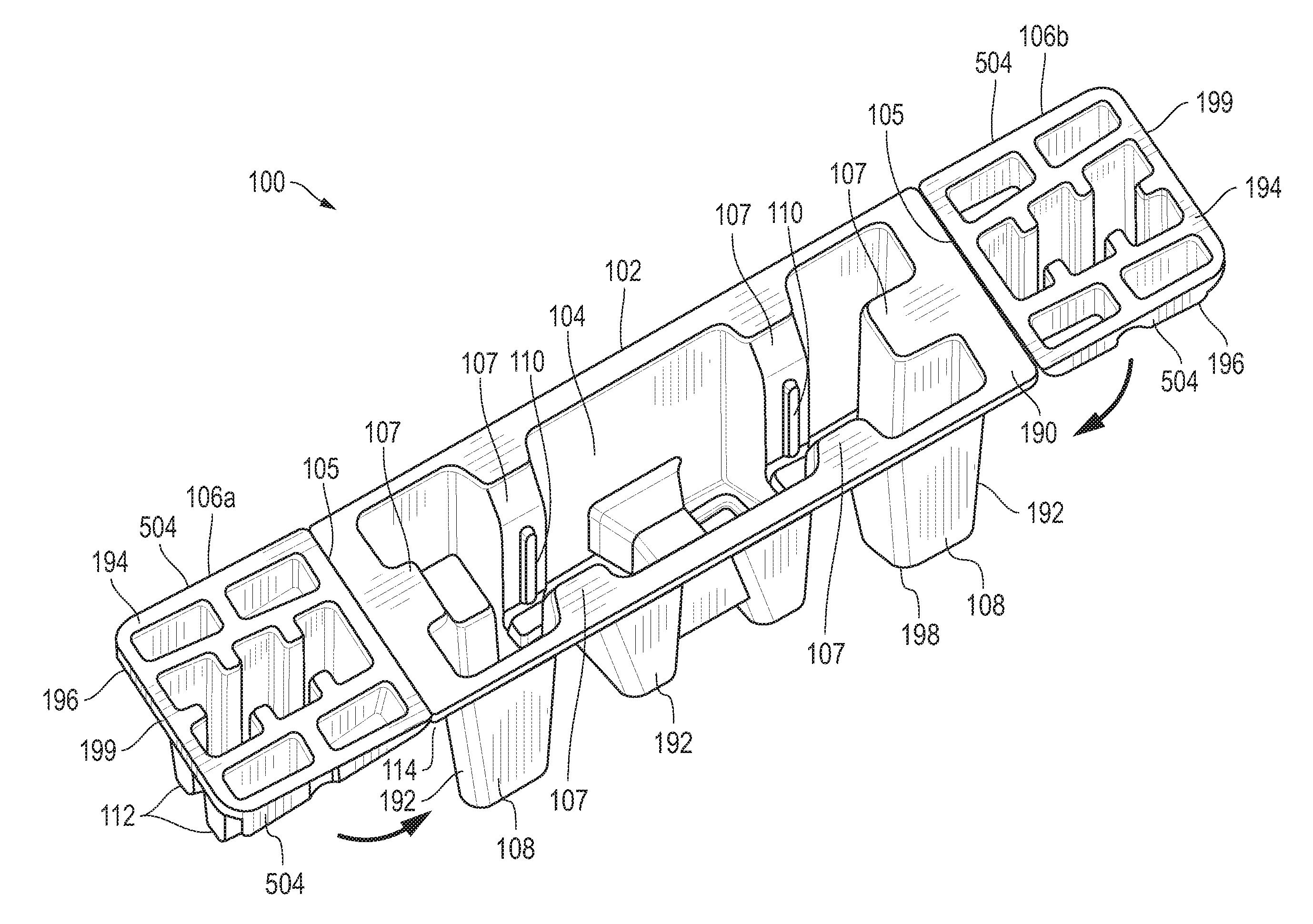
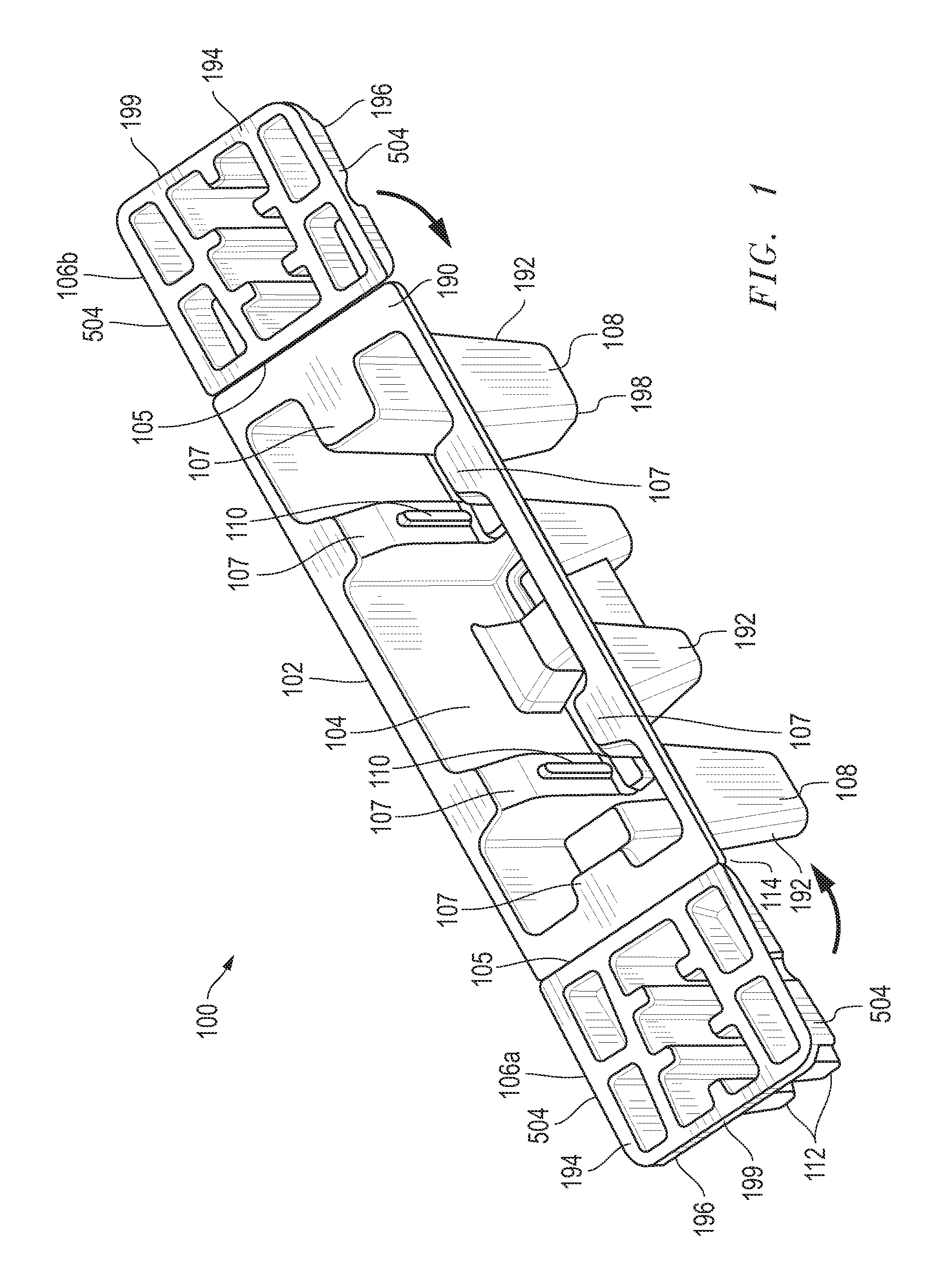
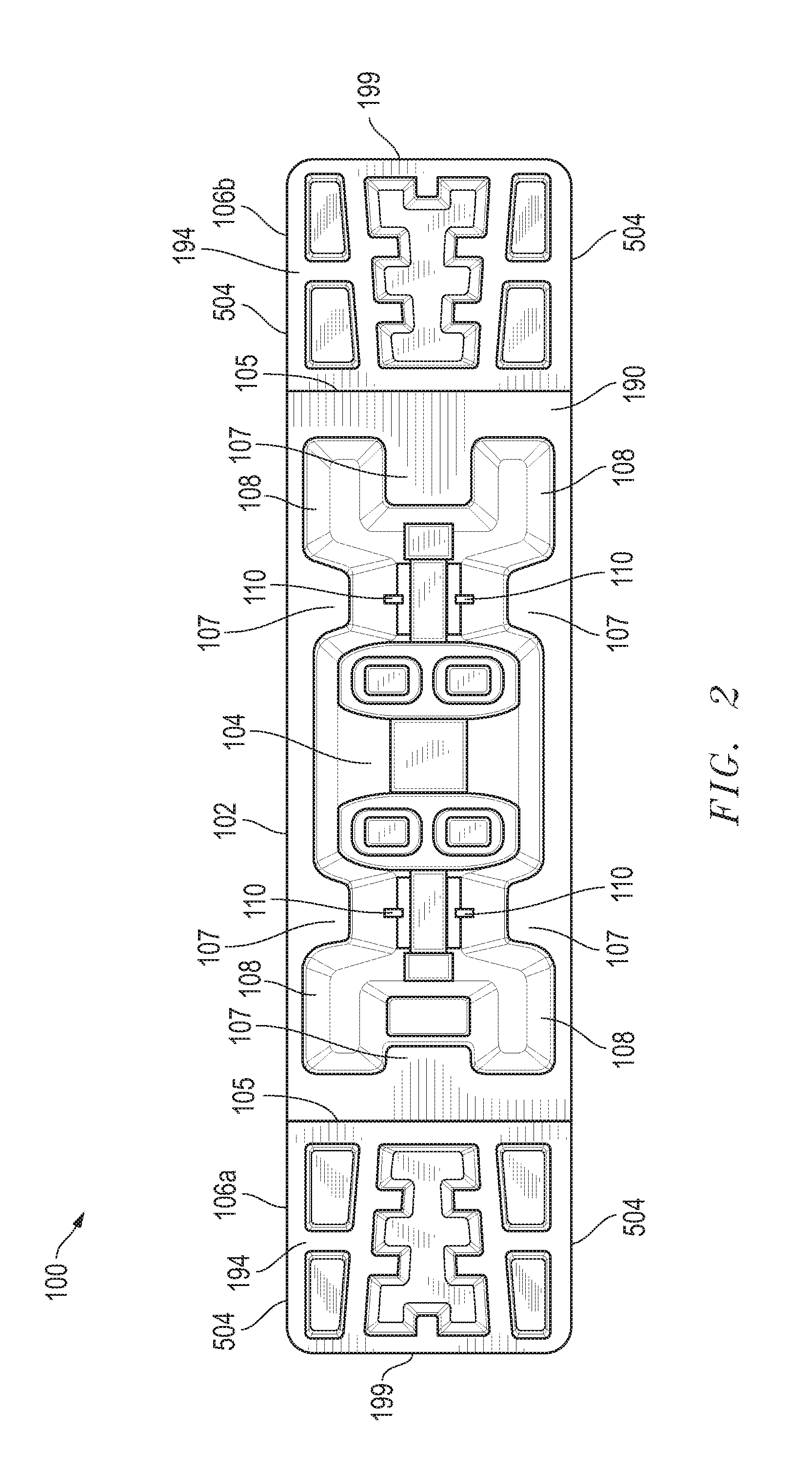
[0024]FIGS. 1 and 2 illustrate a packing device 100 configured for use in packing objects, such as information handling systems and other types of electronic devices. As shown, packing device 100 includes a main packing device section 102 and two foldable buffer sections 106a and 106b that are each hingeably attached by a hinge feature at a respective hinge line 105 to each of two respective opposing peripheral sides 192 of main section 102. In this exemplary embodiment, each hinge line 105 is formed at the intersection of a peripheral side 192 and opening side 190 of main section 102. Foldable buffer sections 106a and 106b are shown in outward extended position in FIGS. 1 and 2.

[0025]In this exemplary embodiment, opening side 190 of main section 102 has a peripheral portion that is co-planar to a corresponding peripheral portion of the first side 194 of each respective buffer section 106a and 106b, although this is not necessary. It will also be understood that although FIGS. 1 and...


PUM

PropertyMeasurementUnit
Forceaaaaaaaaaa
Shapeaaaaaaaaaa
Strengthaaaaaaaaaa

Abstract

Devices and methods for packing objects, including information handling systems and other types of electronic devices that may be implemented using a single piece and assembly-free packing device configuration that has one or more foldable and insertable buffer sections that are foldable to increase the overall strength of the packing device against external loads and shocks.

Description

FIELD OF THE INVENTION[0001]This invention relates generally to packing devices, and more particularly to packing devices having packing buffers.BACKGROUND OF THE INVENTION[0002]As the value and use of information continues to increase, individuals and businesses seek additional ways to process and store information. One option available to users is information handling systems. An information handling system generally processes, compiles, stores, and / or communicates information or data for business, personal, or other purposes thereby allowing users to take advantage of the value of the information. Because technology and information handling needs and requirements vary between different users or applications, information handling systems may also vary regarding what information is handled, how the information is handled, how much information is processed, stored, or communicated, and how quickly and efficiently the information may be processed, stored, or communicated. The variati...

Claims


Application Information

Patent Timeline
IPC IPC(8): B65D81/02B65B5/00
CPCB65D5/5069B65D2585/6837B65D81/05B65D5/5088
Inventor OOI, WAI KEKCHUAH, HWA BEE
Owner DELL PROD LP
Learn More