Cross-Sectionally Morphing Airfoil

Inactive Publication Date: 2012-05-03
RIX MATTHEW BOYD
View PDF21 Cites 21 Cited by
  • Summary
  • Abstract
  • Description
  • Claims
  • Application Information

AI Technical Summary

Benefits of technology

[0009]This morphing airfoil was designed to allow optimal airfoil performance during all phases of flight including but not limited to takeoff, cruise, loiter and landing. Design criteria required a smooth transition between two airfoils while maintaining structural rigidity. Other design goals included mechanical simplicity and low overall weight.
[0010]The present invention includes a structural main spar with a mechanism that rotates a split or elastic upper and/or lower surface to allow the airfoil camber and chord to vary. Applied to an aircraft, the present invention has several applications including but not limited

Problems solved by technology

And in turn, an airfoil that provides a large amount of lift at low speeds will allow an airplane to land on very small airstrips but limit the aircraft speed and fuel economy at cruise.
This increases or decreases lift (and/or

Method used


Image

  • Cross-Sectionally Morphing Airfoil
  • Cross-Sectionally Morphing Airfoil
  • Cross-Sectionally Morphing Airfoil

Examples


Example

[0013]It should be understood that the present invention is not limited to the aerospace application described in this embodiment. It may be adapted to include, but not limited to, any other aerospace application, ground vehicle application, watercraft application, or any other use and / or application of an airfoil.

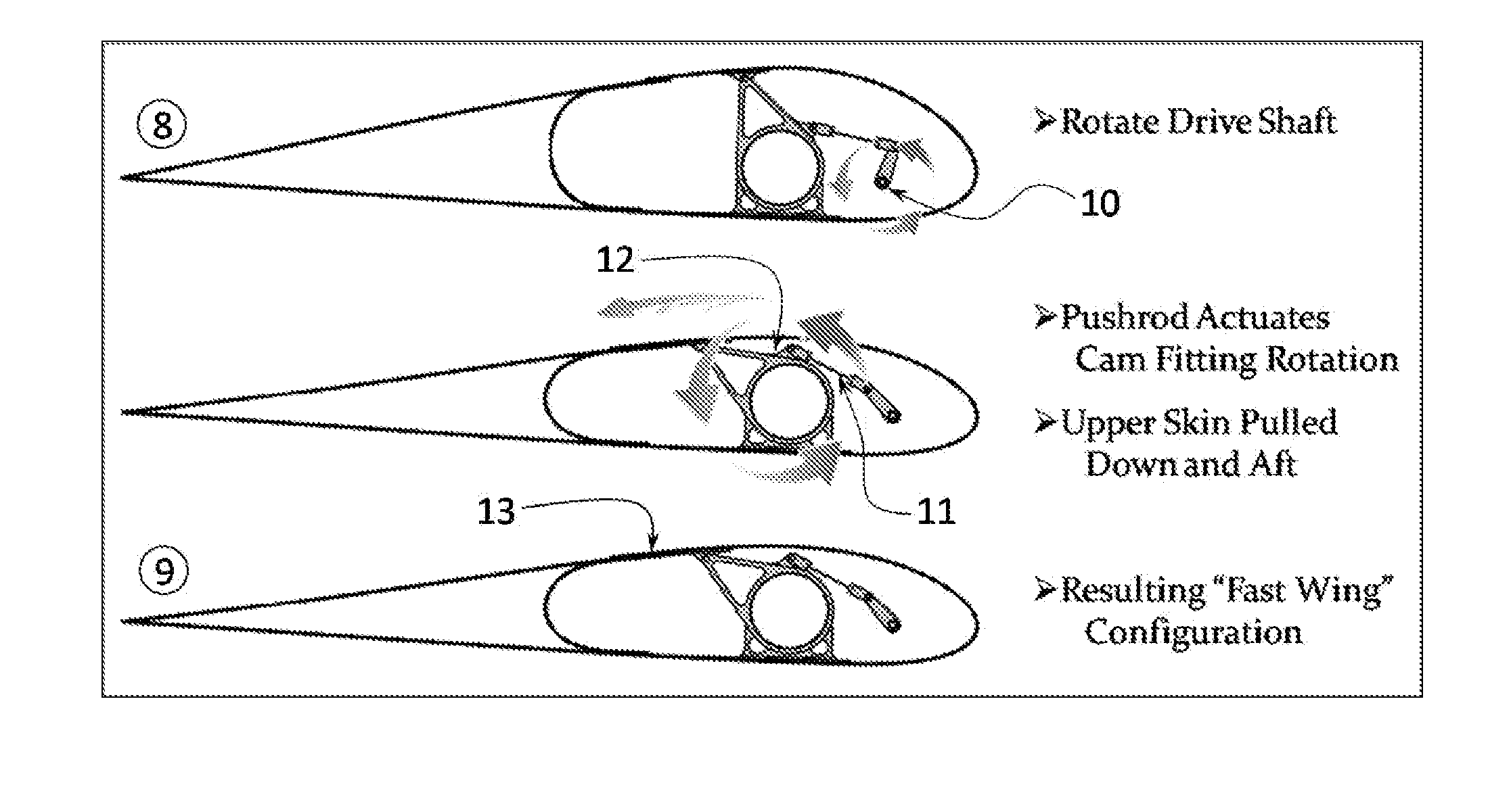
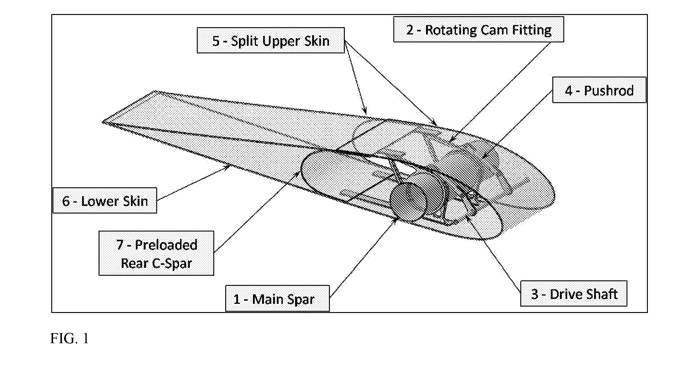
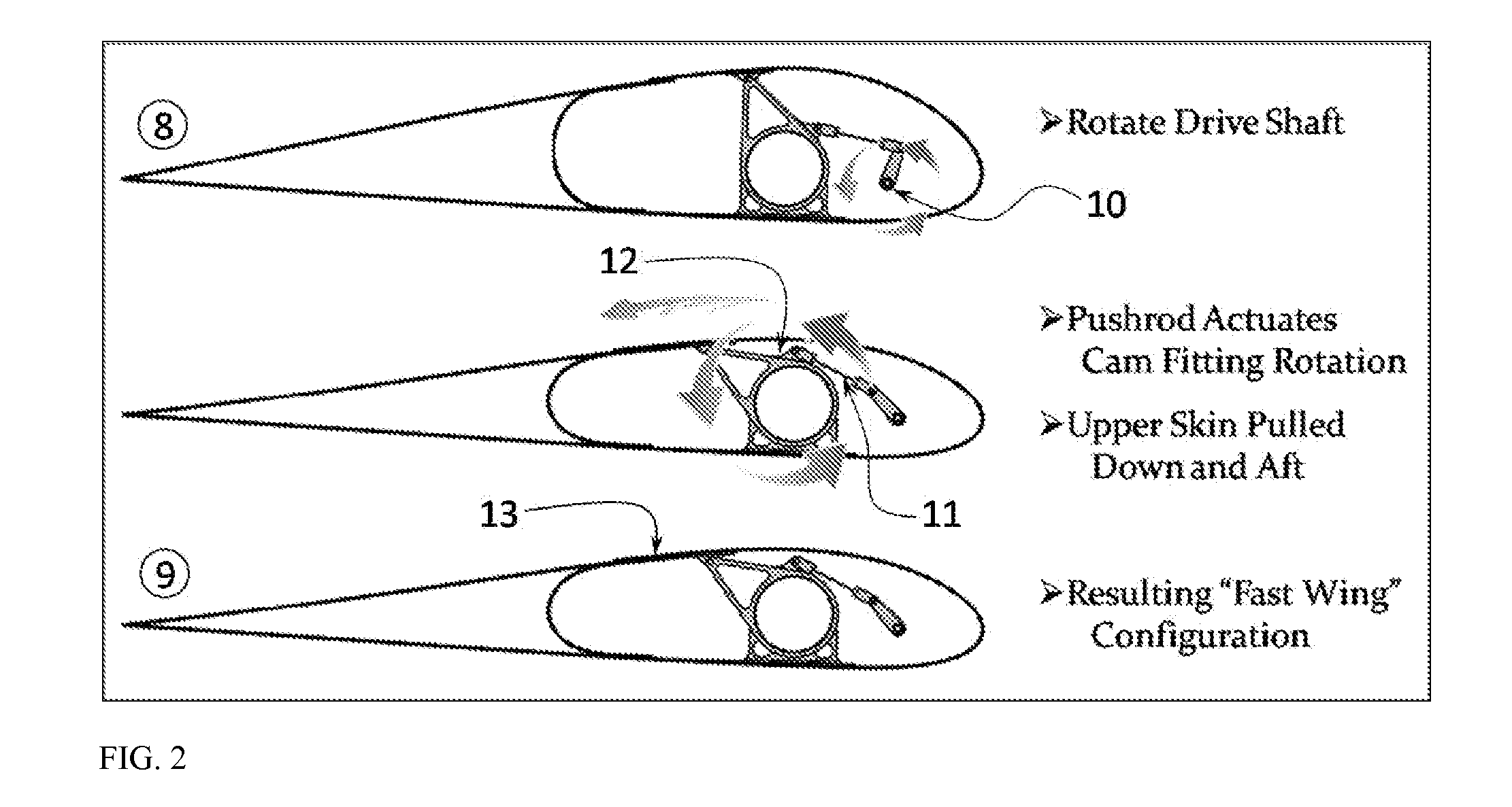
[0014]FIG. 1 is a perspective view of a wing section that utilizes a morphing airfoil in accordance with the embodiment of the present invention. The embodiment of the present invention includes a main spar (1) that allows for a rotational fitting (2) to pivot with the rotation of a drive shaft (3). The rotation is shown in this embodiment as being driven by a drive shaft (3) translating a push rod (4), however it should be understood that the present invention is not limited to this method of imposed rotation. The present invention would include any form of input that would result in the desired upper skin (5) motion or change in shape and / or camber.

[0015]In this embodime...


PUM


Abstract

The present invention provides an apparatus, system, and method for morphing the cross-sectional shape of an airfoil between a high-speed, low-lift airfoil and a low-speed, high-lift airfoil, including interim airfoil configurations, to allow for optimal performance. This is done by inputting a control command into the system that alters the shape of the split or elastic upper and/or lower skin surface to allow the airfoil camber and chord to vary.

Description

CROSS-REFERENCE TO RELATED APPLICATIONS[0001]Not ApplicableSTATEMENT REGARDING FEDERALLY SPONSORED RESEARCH OR DEVELOPMENT[0002]Not ApplicableREFERENCE TO SEQUENCE LISTING, A TABLE, OR A COMPUTER PROGRAM LISTING COMPACT DISC APPENDIX[0003]Not ApplicableTECHNICAL FIELD[0004]The present invention relates generally to aeronautical vehicle systems and more specifically to the shape and composition of an airfoil and a method for altering the cross-sectional shape and / or size of the airfoil.BACKGROUND OF THE INVENTION[0005]An airfoil is the cross-sectional shape of a lifting body. When designing a lifting body, the airfoil is selected to allow the lifting body to perform optimally for its primary mission. There are always tradeoffs between different airfoils. For example, in an airplane application, an airfoil chosen for a high-speed airplane will inherently require a longer runway and higher airspeeds when landing due to the lower total lift produced. And in turn, an airfoil that provide...

Claims


Application Information

Patent Timeline
IPC IPC(8): B64C3/44
CPCB64C3/48Y02T50/145B64C2003/445Y02T50/10
Inventor RIX, MATTHEW BOYD
Owner RIX MATTHEW BOYD
Why Eureka
Try Eureka