Transducer

a transducer and capacitive technology, applied in piezoelectric/electrostrictive/magnetostrictive devices, piezoelectric/electrostriction/magnetostriction machines, electrical equipment, etc., can solve the problems of limiting the performance of these capacitive transducers, affecting the performance of the device, and affecting the operation.

Inactive Publication Date: 2012-05-03
AGENCY FOR SCI TECH & RES
View PDF1 Cites 28 Cited by
  • Summary
  • Abstract
  • Description
  • Claims
  • Application Information

AI Technical Summary

Problems solved by technology

However, the performance of these capacitive transducers may be limited by the intrinsic physical laws.
Capacitive transducers with parallel-plate structure most often suffer design trade-offs such as bandwidth and mechanical sensitivity (e.g. for sensors), thermal noise and passive damping (e.g. for sensors), output power and collapse voltage (e.g. for actuators), etc., which result from the nonlinearity of the electrostatic force.
Furthermore, the intrinsic properties of the electrostatic force may generate “stiffness softening” effect and results in a collapsed structure when the restoring stiffness force fails to maintain or counter the increasing electrostatic force.
The occurrence of collapse for parallel-plate capacitive transducers limits their performance.
For the design trade-off between the transducers' bandwidth and their mechanical sensitivity, in order to expand their bandwidth, the transducers need to be less compliant, which results in the mechanical sensitivity dropdown.
Moreover, the compliance of the tran

Method used


Image

  • Transducer
  • Transducer
  • Transducer

Examples


Embodiment Construction

[0030]The following detailed description refers to the accompanying drawings that show, by way of illustration, specific details and embodiments in which the invention may be practiced. These embodiments are described in sufficient detail to enable those skilled in the art to practice the invention. Other embodiments may be utilized and structural, logical, and electrical changes may be made without departing from the scope of the invention. The various embodiments are not necessarily mutually exclusive, as some embodiments can be combined with one or more other embodiments to form new embodiments.

[0031]In the context of various embodiments, it should be appreciated that embodiments described in the context of one of the devices may be analogously valid for the other device or devices.

[0032]In the context of various embodiments, the phrase “at least (substantially” may include “exactly” and a variance of ±5% thereof. As an example and not limitations, “A is at least substantially sa...


PUM


Abstract

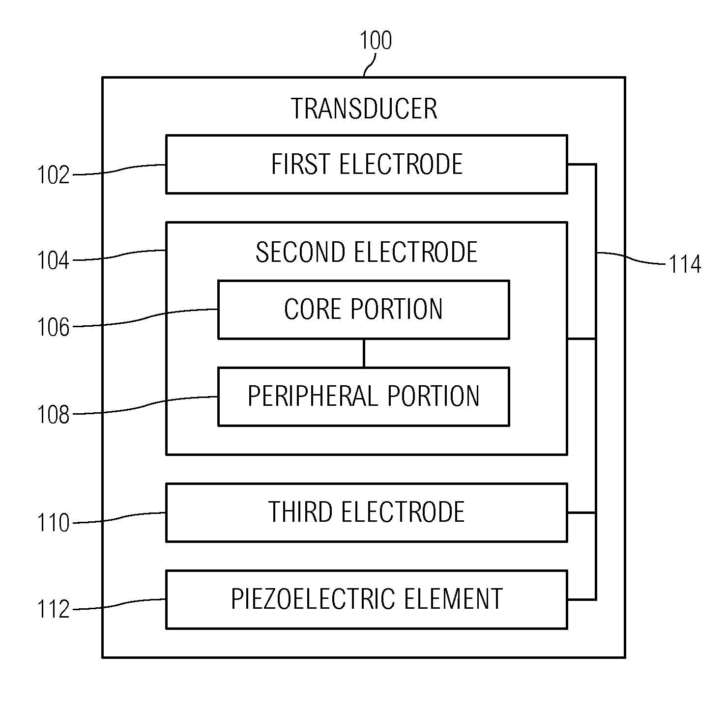
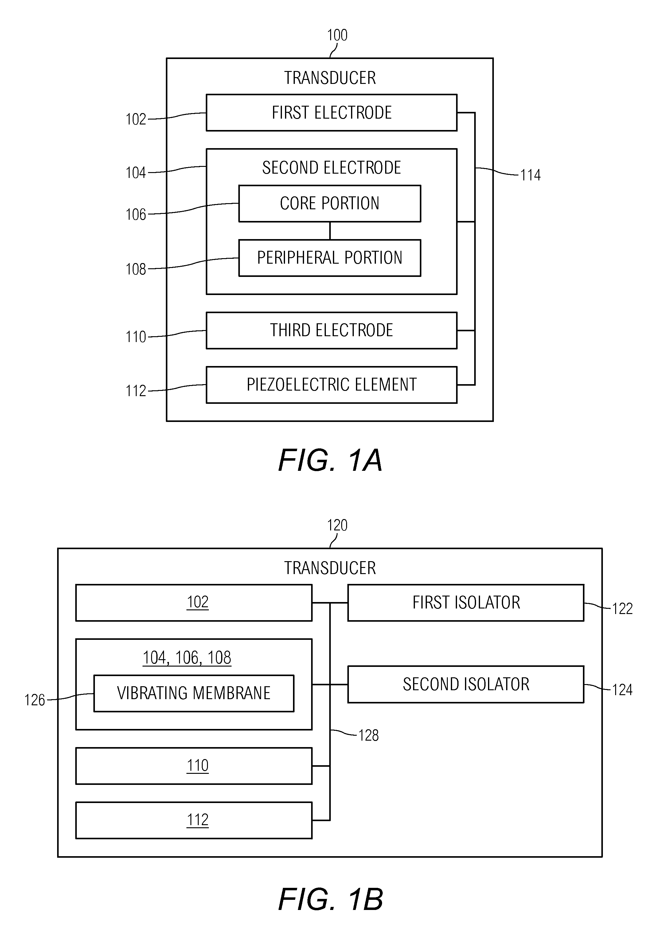
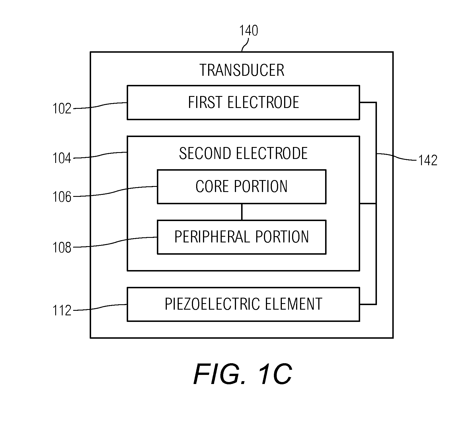
According to embodiments of the present invention, a transducer is provided. The transducer includes a first electrode, a second electrode disposed over the first electrode such that the first electrode and the second electrode form respective capacitive electrodes of a capacitor, the second electrode comprising a core portion and a peripheral portion, a third electrode disposed relative to the second electrode such that the third electrode overlaps with the peripheral portion of the second electrode, and a piezoelectric element disposed between the peripheral portion of the second electrode and the third electrode, so as to tune a tensional force provided by the piezoelectric element onto the second electrode by varying a piezoelectric voltage applied between the second electrode and the third electrode.

Description

[0001]This application claims the benefit of priority of Singapore patent application No. 201006909-4, filed 22 Sep. 2010, the content of it being hereby incorporated by reference in its entirety for all purposes.FIELD OF THE INVENTIONS[0002]Various embodiments relate to a transducer.BACKGROUND OF THE INVENTIONS[0003]Due to the ability of integration with complementary metal-oxide-semiconductor (CMOS) circuitry, wide bandwidth and highly compact size, the micro-machined capacitive transducers have been widely developed as condenser microphones, accelerometers, pressure sensors and ultrasound devices, etc. However, the performance of these capacitive transducers may be limited by the intrinsic physical laws.[0004]Capacitive transducers with parallel-plate structure most often suffer design trade-offs such as bandwidth and mechanical sensitivity (e.g. for sensors), thermal noise and passive damping (e.g. for sensors), output power and collapse voltage (e.g. for actuators), etc., which...

Claims


Application Information

Patent Timeline
IPC IPC(8): H01L41/107H01L41/047
CPCH01L41/0973H04R19/005H10N30/2047
Inventor QU, JINLITSAI, MING LIN JULIUSSOON, BO WOON JEFFREY
Owner AGENCY FOR SCI TECH & RES
Why Eureka
Try Eureka