Control circuit and method for a current mode controlled power converter
a control circuit and power converter technology, applied in the field of current mode control power converters, can solve problems such as inconvenience for users and designers, serious instability of power converters, abnormal operation of connected load, etc., and achieve good stability
- Summary
- Abstract
- Description
- Claims
- Application Information
AI Technical Summary
Benefits of technology
Problems solved by technology
Method used
Image
Examples
first embodiment
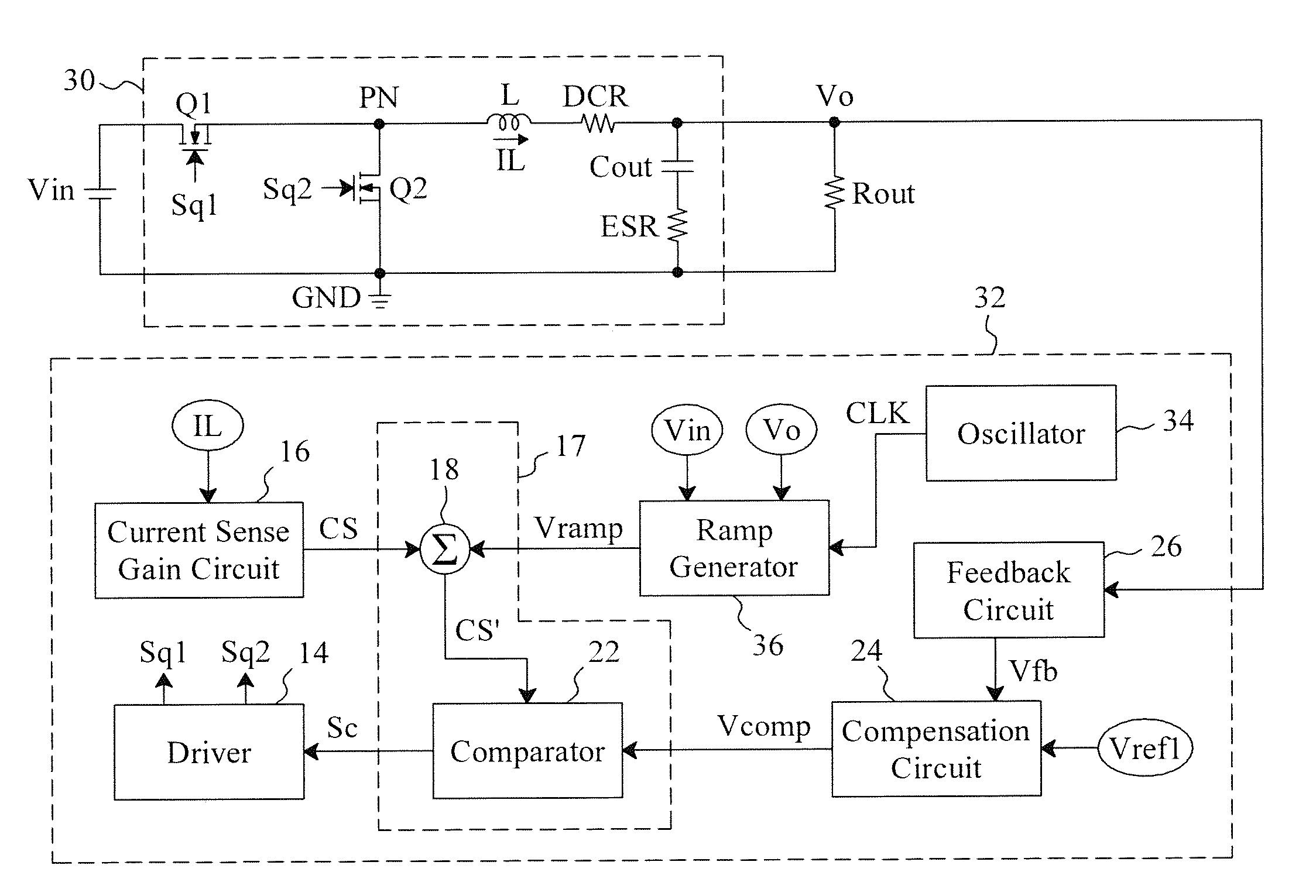
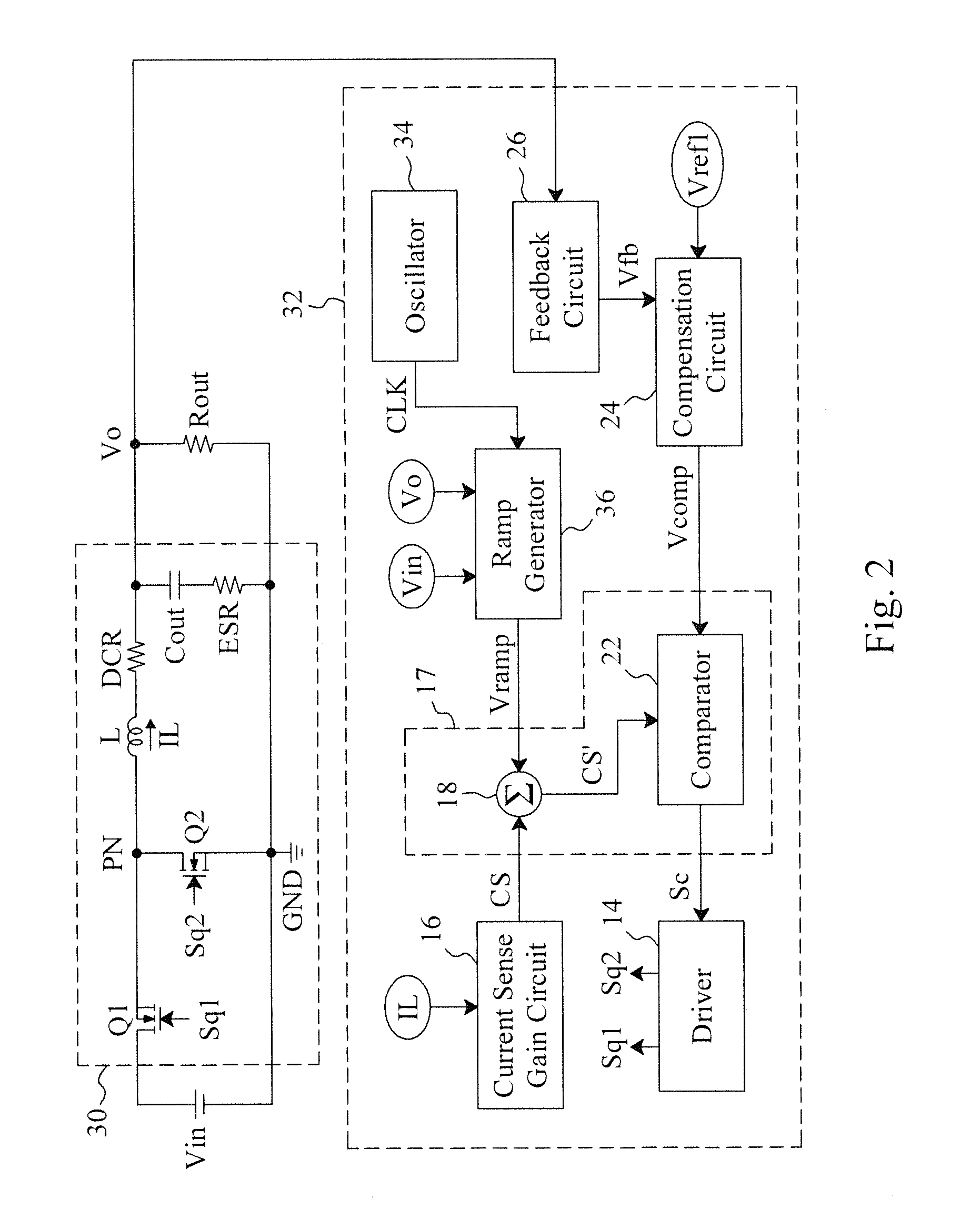
[0027]FIG. 3 is a circuit diagram of a first embodiment for the ramp generator 36 shown in FIG. 2, which includes a voltage divider 40, a voltage controlled current source 42, a switch Q3 and a capacitor Cramp. The switch Q3 is shunt to the capacitor Cramp and switched by the clock CLK for the capacitor Cramp to be charged or discharged to generate the ramp signal Vramp. The voltage divider 40 divides the input voltage Vin to generate an input voltage dependent signal Va. The voltage controlled current source 42 has a positive input terminal receiving a reference voltage Vref2 larger than the signal Va, and a negative input terminal receiving the input voltage dependent signal Va, and provides a charge current I1 for charging the capacitor Cramp responsive to the differential voltage between the reference voltage Vref2 and the input voltage dependent signal Va to adjust the peak of the ramp signal Vramp. As the input voltage Vin decreases, the differential voltage between the refere...
second embodiment
[0028]FIG. 4 is a circuit diagram of a second embodiment for the ramp generator 36 shown in FIG. 2, which includes the same elements 40, 42, Q3 and Cramp as that of FIG. 3, while the voltage divider 40 divides the output voltage Vo to generate an output voltage dependent signal Vb applied to the positive input terminal of the voltage controlled current source 42, and the negative input terminal of the voltage controlled current source 42 is grounded. Thus, the charge current I1 provided by the voltage controlled current source 42, and thereby the peak of the ramp signal Vramp, is adjusted by the differential voltage between the output voltage dependent signal Vb and the ground potential GND. The smaller the output voltage Vo is, the smaller the output voltage dependent signal Vb is, so the smaller the differential voltage between the output voltage dependent signal Vb and the ground potential GND, and thereby the smaller the charge current I1 is, and the smaller the peak of the ramp...
third embodiment
[0029]FIG. 5 is a circuit diagram of a third embodiment for the ramp generator 36 shown in FIG. 2. In addition to the voltage divider 40, the voltage controlled current source 42, the switch Q3 and the capacitor Cramp similar to those shown in FIG. 3, this embodiment further includes a voltage divider 44 for dividing the output voltage Vo to generate an output voltage dependent signal Vb, and a voltage controlled voltage source 46 for generating a differential voltage Vc responsive to the difference between the signals Va and Vb. In this embodiment, since the input voltage Vin is larger than the output voltage Vo, the input voltage dependent signal Va is larger than the output voltage dependent signal Vb. The voltage controlled current source 42 has its positive input terminal and negative input terminal receiving the reference voltage Vref2 and the differential voltage Vc, respectively, and thus adjusts the charge current I1 responsive to the difference between the reference voltag...
PUM
 Abstract
Description
Claims
Application Information
 - R&D
- Intellectual Property
- Life Sciences
- Materials
- Tech Scout
- Unparalleled Data Quality
- Higher Quality Content
- 60% Fewer Hallucinations
Browse by: Latest US Patents, China's latest patents, Technical Efficacy Thesaurus, Application Domain, Technology Topic, Popular Technical Reports.
© 2025 PatSnap. All rights reserved.Legal|Privacy policy|Modern Slavery Act Transparency Statement|Sitemap|About US| Contact US: help@patsnap.com


